
The general definition of a transmission line is “a device that transfers energy from one point to another.” If that is the case, a wire connecting lead used in a DC circuit would satisfy that definition. For DC and low frequency applications (e.g., audio), this is adequate. Typically it is not called a transmission line but simply a wire. Regardless of terminology, it is a transmission line for such applications.
A simple wire lead does not work well for RF and microwave applications due to its large dimensions relative to a wavelength and losses due to the skin effect. To take into account the unique characteristics high frequency transmission lines, a more appropriate definition is “a device used to transfer energy from one point to another efficiently.” An efficient transfer of energy is one with a minimum amount of reflective loss (i.e. close to a perfect match, or VSWR = 1:1), as well as minimum amount of resistive loss due to mechanisms such as the skin effect. This is important at RF and microwave frequencies, because as frequency increases, energy lost in a transmission line is more difficult and costly to recover.
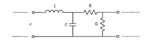
Figure 1 Equivalent circuit of a transmission line.
An equivalent circuit for a section of transmission line is shown in Figure 1. The representation is of only a single section of the transmission line, not the entire line. (The dashed lines on both sides of the figure indicate that there is more transmission line than is shown.) There are four parameters to consider: inductance (L), resistance (R), capacitance (C) and conductance (G). There is also the dielectric constant, ε, of the insulating material in the transmission line. Values for each of the four parameters are expressed in their appropriate units per unit length. The values are expressed per unit length because the equivalent circuit shown in Figure 1 represents only a section of the transmission line; that section length is the unit length. The length can be expressed in any appropriate unit (e.g., ft, m, cm). The value simply indicates what each parameter is for that length of line. The parameters are said to be distributed.
The inductance (microhenries/unit length) in a transmission line is due the current flowing in the metallic conductor. Alternating current (AC) flowing through the conductor produces a magnetic field. The field reaches its maximum at the maximum amplitude of the current flow. When the cycle reverses and begins to go in the reverse direction, the magnetic field collapses, creating an inductive force that produces a current that opposes the applied current. The arrangement of fields sets up an inductance on the transmission line that can be characterized as an inductance per unit length. Inductive reactance, which is the Ohmic result of inductance, increases with frequency and can cause problems for high frequency circuits. Thus, the inductance should generally be kept low for efficient operation.
The resistance (Ohms/unit length) shown in Figure 1 is also associated with the metallic conductor and current flow. Any time current flows through a metallic conductor, there is a loss due to finite resistance in the conductor. This obeys Ohm’s law, which requires a voltage drop across a resistance when current flows through it; thus, the loss in the conductor of a transmission line is caused by current flowing through its resistance causing a voltage drop.
The last two parameters are associated with the dielectric used in the transmission line. The first parameter is capacitance (farads/unit length). A capacitor has two conductive plates of a certain area separated by distance with a dielectric between them. In Figure 1, there are two plates, which are the upper and lower conductors of the transmission line. One plate is the center conductor and the other is the ground, or shield. These plates have an associated area per unit length separated by the dielectric in between, creating a capacitance per unit length. Capacitive reactance, which is a result of the line capacitance, decreases with an increase in frequency and causes the propagating signals to be shorted to ground at certain frequencies. So, the distributed capacitance, as well as the distributed inductance and resistance of transmission lines should, in general, be minimized.
Conductance (siemens/unit length) is the amount of leakage through the dielectric. There is always a certain amount of conductance, because there is no such thing as a perfect dielectric. That means a certain amount of energy passing down the transmission line appears at the other conductor. It usually is a very small quantity, because many dielectrics are very good insulators in transmission line applications. Conductance is represented by a shunt resistor between the signal wire and the return wire (ground).
The term dielectric constant (ε) is the electrical property of the dielectric material that is between the conductors in a capacitor or transmission line. This may be air, Teflon or other material. It is a relative value equal to the ratio of the electric field in a vacuum divided by the electric field in the medium. The insertion of a dielectric medium between capacitor plates increases its capacitance or ability to store opposite charges on each plate. The dielectric constant of air is considered to be 1.
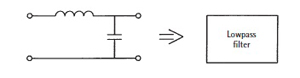
Figure 2 Lossless transmission line.
To further clarify the important characteristics of transmission lines, assume a perfect transmission line, that is, R = 0 and G = ∞. Those values indicate that the resistance of the conductor is so low that it can be ignored and that the dielectric is perfect (no leakage). The result of this assumption is shown in Figure 2, the circuit diagram for a lowpass filter, which is a component that, ideally, passes all electromagnetic energy below a certain frequency (its cutoff frequency) and attenuates everything above that frequency. With this characteristic, a transmission line has some frequency, depending on its individual characteristics, above which it is not useable. Operation above the cutoff frequency results in much higher loss in the transmission line than does operation within its specified frequency range. A transmission line, when used to connect circuits, should be nearly transparent or invisible. That is, the line physically and electrically connects circuit components but its effect on circuit operation is minimal.