
Common performance measures associated with microwave transmission lines and circuits are VSWR, reflection coefficient and return loss, as well as transmission coefficient and insertion loss. These may all be expressed using scattering parameters, more commonly referred to a S-parameters.
VSWR
Visualize a rope tied to a door handle. If you take the untied end in your hand and flip it up and down once, you will see a “wave” going down the rope to the door. If the door and the rope were completely compatible, the wave would disappear into the door. But, as we all know, the wave does not disappear, it comes right back to you. (As a matter of fact, if you do not pay attention to what you are doing, the rope will flip right out of your hand when the wave returns). That is the same condition for an RF signal or a microwave signal as it travels down a transmission line. If the wave goes down the line and the impedance of the load is exactly equal to the characteristic impedance of the transmission line (usually 50 ohms), the signal is completely absorbed into the load and no energy is returned. This is a perfectly matched condition (i.e., VSWR = 1.0:1). If the load impedance is not equal to the characteristic impedance of the transmission line, a portion of the signal sent down the line is reflected back. That signal adds to the incoming signal in some cases and subtracts from it in other cases. This is a property of linear systems called ‘superposition’. The result of the addition and subtraction is a wave that “stands still” on the line, thus the term voltage standing wave ratio. It is called a ratio because it is the comparison of the maximum amplitude of the voltage in the standing wave (anti-node) to its minimum amplitude (node) (see Figure 1).
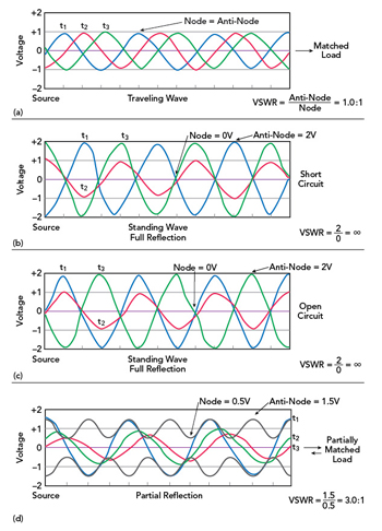
Figure 1 VSWR examples; traveling wave (a), standing wave with short circuit termination (b), standing wave with open circuit termination (c), standing wave with partial reflection (d).
This is an important measure because energy in a microwave system is transferred through traveling waves. Reflection impedes the forward flow of energy from a source to a load and is normally undesirable. A familiar example is the use of a microwave oven for cooking. In normal operation, much of the energy from microwave radiation generated by a magnetron is absorbed by the food placed within the oven’s cavity. Reflections are minimized because the food provides a suitable impedance match. If, however the oven is operated with no food item present, the energy is reflected off the conducting walls and back to the source, creating standing waves. The standing waves create regions of large voltage peaks that can cause arcing and damage to the magnetron.
Since the comparison is between voltages, the VSWR value has no units and it is a ratio compared to 1. The best value is a 1.0:1 ratio. That means the load and the transmission line are the same impedance. The other extremes are an open circuit and a short circuit. With an open circuit, virtually all the energy sent down the line is reflected back because it has no other place to go. Theoretically, all the energy is reflected. In practice, a small amount is radiated out the open end of the line. A short circuit also reflects all the energy sent down the line. That is because no voltage can be developed across a short circuit. So there is no signal to be sent to a load. A short circuit is often desirable. It is a way of knowing the exact location of a component at the end of a transmission line and sets up a reliable reference point for all the measurements that need to be taken; a short circuit represents an extreme case when looking at the VSWR of a device or circuit.
The VSWR for both an open circuit and a short circuit is ∞. That, of course, is the largest theoretical value possible. In practice, VSWRs of 10:1, 20:1, or 25:1 are indications of something like an open- or short-circuit condition. A VSWR of infinity is a theoretical value that in practice cannot be achieved. Everything between an open- or short-circuit condition and a perfect match is a number that is a ratio compared to 1. Those numbers will be between 1:1 and ∞, depending on the degree of mismatch in the system.
It is difficult, if not impossible, to achieve a perfect 1:1 match in a practical circuit. A 1.5:1 or a 2:1 match, is usually sufficient. Some devices achieve 1.2:1 or slightly lower, but that is about as low as one might see in everyday applications. Connectors will exhibit VSWRs on the order of 1.05:1, since the connectors used on a transmission line should minimally influence a circuit’s operation.
Reflection and Transmission Coefficients
Reflection coefficient is the fraction of an incident signal reflected back from a mismatch. The reflection coefficient is expressed as either ρ or Γ, but these symbols may also be used to represent VSWR. It is directly related to the VSWR by
| Γ| = (VSWR - 1)/(VSWR + 1) (1)
That is the fraction of a signal reflected back by the load impedance, and is sometimes expressed as a percentage.
For a perfect match, no signal is reflected by the load (i.e., it is totally absorbed), so the reflection coefficient is zero. For an open or short circuit, the entire signal is reflected back, so the reflection coefficient in both cases is 1. Note that this discussion deals only with the magnitude of the reflection coefficient. Γ has an associated phase angle as well, which distinguishes between a short circuit and an open circuit, as well as all states in between. For example, reflection from an open circuit results in a 0 degree phase angle between the incident and reflected wave, which means that the reflected signal adds in phase with the incoming signal at the open circuit location; i.e. the amplitude of the standing wave is double that of the incoming wave. In contrast, a short circuit results in a 180 degree phase angle between the incident and reflected signal, which means that the reflected signal is opposite in phase to the incoming signal, so their amplitudes subtract, resulting in zero. This can be seen in Figures 1a and b.
Where the reflection coefficient is the fraction of an incident signal reflected back from an impedance mismatch in a circuit or transmission line, the transmission coefficient is the fraction of the incident signal that appears at the output. It is a function of the signal that is reflected as well as internal circuit interactions. It has a corresponding amplitude and phase, as well.