
The outer conductor serves two functions. It is a ground reference for the signal on the center conductor and is also a shield. The shield keeps external signals out and internal signals in. The braid construction may be single, double or triaxial (two braids separated by an insulator). The single-braid construction consists of bare, tinned or silverplated copper wires. The double braid consists of two single braids with no insulation between them. Triaxial construction consists of two single braids with a layer of insulation between them. The type and the degree of shielding needed for a particular application determines which scheme is best. It may depend, in whole or in part, on the environment, the type and amplitude of signals and/or cost factors. A variety of shielding types are available to fit most applications.
The outer coating provides environmental protection for the cable. Viewing the outer coating, several popular cables; RG-58, RG-59 and RG-62 cables may seem nearly identical (see Table 1), although they have distinctively different electrical characteristics.
| Cable Type | Z (Ω) | Outer-Coating Diameter (in.) | Outer-Conductor Inner Diameter (in.) | Inner-Conductor Outer Diameter (in.) |
| RG-58 | 50 | 0.195 | 0.150 | 0.083 |
| RG-59 | 75 | 0.242 | 0.191 | 0.031 |
| RG-62 | 93 | 0.242 | 0.191 | 0.025 |
Flexible cables are available in a variety of different types and usually have an RG prefix (military designation for cables). The overall cable outside diameter can range from 0.078 (5/64) to over 1 in. Often, the size of the cable is dictated by the CW power handling requirement (continuous wave (CW) is the type of signal characterized by an uninterrupted AC sine wave). Other times, the size is dictated by such factors as installation area (does it need to bend around many corners?) or environmental conditions (both atmospheric and electrical). As with any choice, the application and its specifications dictate which cable to use. No single cable is suitable for every job.
These transmission lines are flexible and able to be bent around corners and into tight areas. However, even flexible cables have a minimum bend radius, that is, a radius beyond which bending the cables results in serious performance degradation; they cannot be tied in a knot and be expected to perform as well as when stretched out straight. Consult the cable data sheet to determine its minimum bend radius.
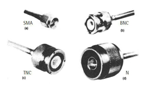
Figure 6 Flexible coaxial cable assembly with connectors (Source: Thomas S. Laverghetta, Modern Microwave Measurements and Techniques, Artech House, Norwood, Mass., 1988.)
Flexible coaxial cables have many applications, ranging from finished RF cables for equipment shipped to a customer to the typical 50 Ohm cables hanging in every electronics lab. The performance of the final, assembled flexible transmission line depends not only on the cable, itself, but also on the connectors placed on each end. There are many types of connectors that can be attached to a flexible cable. A great deal of care must be taken in the choice of a connector to go on the ends of a flexible cable. The wrong connector can completely cancel all the benefits a good cable choice.
Four typical ones are shown in Figure 6. The subminiature A (SMA) connector (Figure 6a) is used for many microwave applications and comes in a variety of configurations, such as with two- and four-hole flanges for attachment to a chassis. The one shown in Figure 6a is the type used for cable connection. Figure 6b is a BNC connector, a type seen frequently on flexible cables in electronic laboratories. They are good for low frequency applications. Higher frequency circuits and systems should not use BNC connectors because the ground connection is not adequate when the frequency increases. The TNC connector (Figure 6c) is an improved version of the BNC connector for use in higher frequency applications. It is actually a BNC connector with threads, which provides a much better ground connection. The N connector (Figure 6d) is a larger connector suitable for a wide variety of applications over a large range of frequencies. It also has threads for ground connection and can be fitted to a number of flexible cable types.
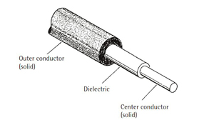
Figure 7 Coaxial cable connector types; SMA (a), BNC (b), TNC (c), N (d).
Semi-rigid coaxial transmission lines
The dictionary defines rigid as “not bending or being flexible, stiff.” Semi-rigid, on the other hand, is something that is fairly solid but capable of being bent. At first sight, a semi-rigid coaxial transmission line (cable) appears rigid. It does, with some effort, however, bend to a specific bend radius and subsequently holds its shape (as if rigid). Once a semi-rigid cable has been bent into shape, however, it should not be re-straightened or re-bent. This will likely change the physical properties of the cable and thus change its electrical properties, as well. For example, multiple bend operations may induce a sharp corner in the center conductor center rather than a smooth bend. The impedance will be different at the corner, causing reflections that degrade performance. Semi-rigid cable, like flexible cable, has a minimum bend radius specified in the manufacturer’s data sheet.
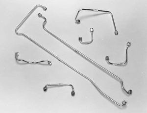
Figure 8 Semi-rigid coaxial cable.
Semi-rigid cable consists of a solid center conductor, a solid dielectric and a solid outer conductor. Every part of a semi-rigid cable is solid, giving it its rigid appearance and characteristics. From Figures 4 and 7, you can see the similarities between semi-rigid and flexible cables. There is a coaxial construction for both transmission lines, i.e., a center conductor is surrounded by a dielectric with an outer conductor used for ground over the entire line. Figure 8 is a typical semi-rigid cable. The main difference between semi-rigid and flexible cable is the solid outer conductor for the semi-rigid cable. The solid conductor improves shielding and gives the cable greater rigidity. The solid outer conductor might be simply a copper sheath over the entire cable or it might be plated for specific applications. Often the cable is gold plated to reduce oxidation of the copper over time, adding to the performance, and to the price. Other cables may be tin-lead plated for the same purpose.