
Figure 16 Microstrip assembly.
Coplanar waveguide
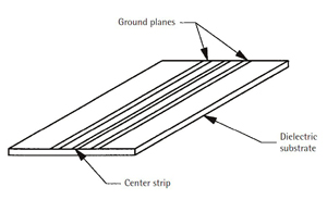
A representation of coplanar waveguide is shown in Figure 16. At first glance, it resembles microstrip construction. It has a single circuit board, like microstrip; it has the circuit traces on the top of the board, like microstrip; and it has air over the top of the circuit board, like microstrip. Looking at it a little closer, however, one sees some distinct differences.
In microstrip construction, there is a circuit trace on top of the board material of a certain width and thickness along with a complete ground plane on the reverse side of the board. In a coplanar waveguide, there is still a circuit trace on the top of the board that is a certain width and thickness, but there are also ground planes on both sides of the circuit trace and, as can be seen in Figure 16, there is no ground plane on the bottom of the circuit board. The ground plane on both sides of the circuit trace is where the transmission line structure gets its name. It is also possible to construct coplanar waveguide as it is shown in Figure 16 but with a complete ground plane on the reverse side. This ground-backed coplanar waveguide is shown in Figure 17 along with conventional coplanar waveguide.
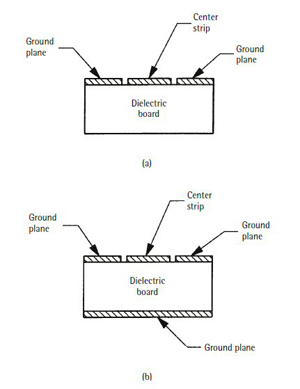
Figure 17 Coplaner waveguide.
One of the properties of coplanar waveguide that makes it attractive for RF and microwave applications is the fact that both series and shunt elements can be attached to the transmission line with relative ease. In the case of microstrip or stripline, the fabrication of such elements can be difficult. With coplanar waveguide, the ground plane is adjacent to the center strip carrying the signal, and connections to it are straightforward.
Waveguide
Usually when we think of waveguide, we think of frequencies well up into the GHz range. We also picture rectangular pieces of hardware with flanges screwed together and that exhibit very low losses. It may be difficult to visualize how it works because there is no center conductor (as in coaxial transmission line) for energy to travel. This is because the energy travels similar to the way it propagates in free space, but is guided by multiple reflections off the waveguide walls.
While every transmission line is a waveguide since it provides a path to “guide” electromagnetic waves down the line, the term waveguide is commonly reserved for what might be called a hollow-pipe waveguide, or at least a waveguide in which two distinct conductors are not present. The “open space” of the waveguide is where the electromagnetic energy finds the path of least resistance and can propagate (or move) down the line to get to its destination. Waveguide is used at microwave frequencies (particularly at higher microwave frequencies) for two reasons: it is often easier to fabricate than coaxial lines; and it often exhibits less loss. Coaxial transmission lines require center conductors that are supported by a dielectric material; waveguide requires no center conductor, its dielectric is air.
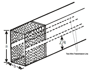
Figure 18 Cross sections of coplanar waveguide (a), and ground-backed coplanar waveguide (b).
One way to describe a rectangular waveguide is to start from a two-wire transmission line as illustrated in Figure 18. The two-wire transmission line is just as the name implies, two wires separated by a dielectric (air in this case). It can be seen from the figure that two adjacent points (one on each wire) are extended to be one-quarter wavelength long, above and below the lines. The two points are then connected to form a short circuit (low impedance). Due to the periodic nature of the RF waveform, at quarter wavelength distance from the short circuit (at the connections to the transmission line) the short circuit is transformed to a high impedance. This is referred to as a quarter-wave stub. Since the short appears as a high impedance in the center of the structure, there is no effect on the transmission of power. If the number of stubs is increased infinity, while the spacing of adjacent stubs is reduced to zero, a rectangular waveguide is formed.
The two dimensions (a and b) are important. The a dimension cannot be less than one-half wavelength. This is because the guide is made up of two quarter-wavelength stubs separated by a small distance. Electromagnetic radiation with l/2 greater than or equal to 2a cannot propagate. The frequency for which 2a is exactly l/2 is called the cutoff frequency, fc. The a and b dimensions are related, as well; the b dimension is slightly more than half of the a dimension.
To understand nature of waveguide, one must visualize a wave (an electromagnetic wave) and not think about voltages and currents. The wave of interest in coaxial transmission lines, microstrip and stripline is the transverse electromagnetic wave (TEM). This is an electric wave and a magnetic wave propagating down the line alternately exchanging energy between electric and magnetic fields. These waves are 90° apart and propagate together with their fields transverse to the direction of propagation.
In conventional rectangular waveguide, either the electric field is transverse to the direction of propagation, i.e. transverse electric (TE) or the magnetic field is transverse to the direction of propagation, i.e., transverse magnetic (TM). In addition to the TE or TM designation, subscripts are used to describe the electric and magnetic field configuration. The general representation is TEmn and TMmn where the subscript “m” indicates the number of half-wave variations of the electric (or magnetic) field along the “a” (wide) dimension of the guide and the subscript “n” is the number of half-wave variations of the electric (or magnetic) field in the “b” (narrow) dimension. The most common mode of operation is the TE10 mode.
The term characteristic impedance is used in describing other forms of transmission lines. For waveguide there is a corresponding term called characteristic wave impedance. This is a representation of the ratio of the electric field and the magnetic field at a certain point in the waveguide. Where the characteristic impedance of a coaxial line is an important parameter, the characteristic wave impedance for waveguide is seldom determined or used, if it is available, since it only characterizes the guide at a certain point. The only place where it might be of value is where the waveguide interfaces with other components in a circuit.
Summary
The transmission lines covered in this section illustrate the need for special structures for RF and microwave use. With these high frequencies, it is no longer possible to think of an interconnection between two circuits as simply a piece of wire that is wrapped or soldered to make the connection. There is a requirement for a low-loss connection for use in this range, and that low-loss connection is the transmission line.