
Since the earliest days of radar, many techniques have emerged for simulating radar targets for a variety of applications.1,2 Recently, there is renewed interest in simulated radar targets for the development of new applications at mmWave and THz frequencies.3,4,5 There is also a growing need for low-cost target simulators to support radar system tests during manufacturing and when calibrating or servicing radar systems in the field.6 This article presents some basic concepts that may be applied to the design and operation of low-cost radar target simulators using directional antennas.
A single directional antenna may be used as a radar target by terminating its I/O port in a manner that causes some, or all, of the received power to be radiated back toward the radar system. In the simplest case, the antenna is terminated with a short circuit or another fixed impedance that is intentionally mismatched to the antenna impedance, thereby generating a reflected radar signal (see Figure 1).
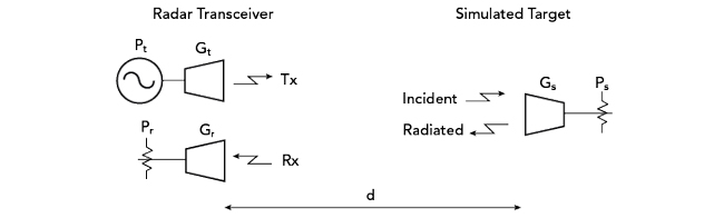
Figure 1 Monostatic radar with a reflecting antenna simulating a target.
Assuming negligible backscattering from the antenna structure itself, the effective radar cross-section (RCS) is a function of the gain of the antenna used to simulate the radar target, as well as the fraction of received power reflected back to the antenna port and transmitted toward the radar. By analyzing the signals involved, the effective RCS of the target antenna is readily determined.
The well-known Friis transmission equation7 describes the RF power exchanged between a transmitter and a receiver. It states that the ratio of the received power, Prx, to the transmitted power, Ptx, is equal to the product of the effective areas of the transmit and receive antennas divided by the distance squared and the wavelength squared:
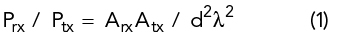
where Atx and Arx are the effective areas of the transmit and receive antennas, d is the distance between the antennas and λ is the wavelength.
The effective area of an antenna, Aeff, is given as:
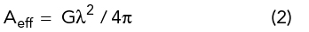
where G is the antenna gain.
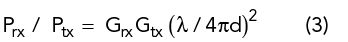
Substituting antenna gains for the effective areas in the Friis transmission equation produces another familiar equation:
For the case of an antenna used to simulate a radar target, the following equation applies:
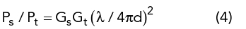
where Ps is the power received by the target simulator antenna, Pt is the power transmitted by the radar, Gs is the gain of the target simulator antenna and Gt is the gain of the transmit antenna.
If all the power received by the target simulator antenna is reflected and retransmitted back toward the radar, the reflected power received by the radar, Pr, is given as:
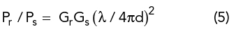
where Gr is the gain of the radar receiver antenna.
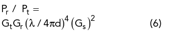
Combining Equations (4) and (5) yields the fraction of transmitted power received by the radar:
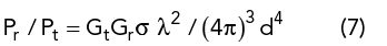
The fraction of transmitted power received by a radar system is also commonly expressed in terms of the target’s RCS, which is usually denoted using the symbol δ:8
Combining Equations (6) and (7) produces the effective RCS of the simulated target in terms of the gain of the target antenna, assuming total reflection of the received signal:
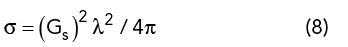
Equation (8) indicates that an antenna configured for total reflection of the received signal back toward the radar has an RCS equal to the antenna’s effective area multiplied by its gain:
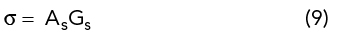
where As is the effective area of the reflecting antenna.
The analysis thus far assumes that the radar is responsive to co-polarized reflections. If the radar responds to cross-polarized signals or some other transformation of the transmit polarization, separate receive and transmit antennas may be used to achieve the desired response polarization.
If the power retransmitted by the target antenna is not equal to the received power, but instead is reduced by an attenuation factor, ks, the RCS of the reflecting antenna is reduced by that factor:
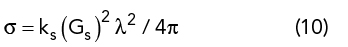
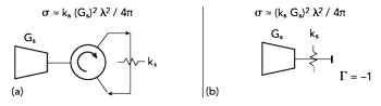
Figure 2 Radar target simulator with adjustable RCS: three-port circulator functioning as a signal diplexer (a) and adjustable attenuator between the reflecting antenna and a short-circuit termination (b).
Two possible configurations for a simulated target with adjustable RCS are shown in Figure 2. In Figure 2a, a three-port circulator functions as a signal diplexer. It passes the received signal through an adjustable attenuator and routes the attenuated signal back to the antenna. The range of RCS that is achievable using such a configuration may be limited by the performance of the circulator. Imperfect impedance matching or signal leakage between ports will determine the minimum reflected signal. In practice it may be difficult to achieve both a wide range of RCS and a flat frequency response using this configuration.