In Figure 2b an adjustable attenuator is placed between the reflecting antenna and a short-circuit termination. If the antenna impedance is well-matched to the attenuator impedance, a wider range of RCS may be realized with this configuration; however, the antenna structure itself produces some backscattering that may determine the lower limit for the effective RCS of the simulated target.
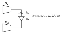
Figure 3 Radar target simulator with adjustable RCS and two antennas.
The attenuator in Figure 2a may be replaced with an amplifier to increase the RCS of the simulated target. Signal leakage through the circulator, as well as various impedance mismatches in the system, will limit how much amplifier gain can be supported while avoiding oscillation.
Improved performance may be achieved using separate transmit and receive antennas for the simulated target (see Figure 3). For such a configuration, the RCS may be estimated as:

where ka is the amplifier gain, Gsr is the gain of the target simulator receive antenna and Gst is the gain of the target simulator transmit antenna.
A target simulator that employs either one or two antennas can include a delay function to control the target’s effective distance from the radar. RF-over-fiber systems based on various technologies are readily available, making it possible to implement range delays equivalent to 100 miles or more at frequencies as high as 60 GHz.9
DOPPLER TARGET SIMULATORS

Figure 4 Doppler radar target simulator with adjustable RCS.
A moving target may be simulated by generating a frequency-shifted copy of the received signal and transmitting it back to the radar system. Such a frequency-shifted signal may be produced using a single-sideband (SSB) modulator and a signal diplexer (see Figure 4). Typically a SSB modulator is realized using a balanced quadrature mixer that provides good suppression of the input carrier signal as well as the unwanted sideband.
To achieve effective suppression of the unwanted sideband, the in-phase (I) and quadrature-phase (Q) modulation signals must be offset in phase by 90 degrees at the modulation frequency. Either the upper or lower sideband is selected by providing either a positive or negative phase difference between the I and Q modulation signals. By selecting the upper sideband, the signal returned to the radar is higher in frequency and simulates decreasing distance between the radar and the target. Conversely, selecting the lower sideband produces a lower frequency return signal that simulates increasing distance.
Assuming negligible signal loss in the signal diplexer and negligible impedance mismatches, the RCS of a single-antenna Doppler target simulator may be estimated as:

where km is the conversion loss of the SSB modulator.
The modulation frequency determines the frequency shift applied to the received radar signal. For an actual moving target, the Doppler frequency shift is twice the closing velocity divided by the wavelength of the radar signal. For example, a radar frequency of 35 GHz and a target velocity of 80 mph (36 m/s) result in a Doppler frequency shift of 8.3 kHz. At 77 GHz the Doppler frequency shift at 80 mph would be 18.4 kHz.
To simulate a single target with fixed velocity, the I and Q modulation signals can be obtained from a function generator that provides a phase-offset adjustment for two output channels operating at the same frequency. If the modulation signals have low harmonic content and the modulator is operated within its linear range, harmonic sideband content may be negligible. Otherwise, the target simulator may produce significant sideband harmonics that could be interpreted as additional moving targets.
The magnitude of the frequency-shifted signal can be controlled over a wide dynamic range by adjusting a variable attenuator positioned between the antenna and the signal diplexer. The lower limit of the Doppler signal amplitude does not depend on impedance mismatches or signal leakage. As a result, the Doppler radar target simulator can measure the sensitivity of a Doppler radar system over a dynamic range of 60 dB or more.
DOPPLER RADAR TRANSCEIVER TESTS
In a manufacturing environment, Doppler radar heads can be quickly tested relative to a “golden” unit that has been field-tested and certified as providing adequate sensitivity to a moving target with a known RCS. A typical setup includes an antenna test range or an anechoic chamber with a fixture on one end for mounting the radar head under test (see Figure 5). The target simulator antenna is positioned at the other end of the test range.

Figure 5 Doppler radar test setup.
Calibration of the Doppler radar test system is straightforward. With the “golden” (calibration) radar head installed and the target simulator activated, the apparent Doppler signal produced by the radar head is fed to a frequency discriminator that computes the target velocity. When the signal-to-noise ratio is sufficient, the frequency discriminator produces a valid measurement of the target velocity. During calibration of the test setup, the attenuation value is adjusted upward to a level where the calibration radar unit becomes unable to produce an accurate velocity measurement. The attenuation value is then decreased slowly until a valid velocity measurement is obtained. The attenuation value may be adjusted further to set the minimum level of performance necessary to pass the sensitivity test. The setup is then used to test production units on a pass/fail basis.
The margin by which a radar transceiver passes or fails can be optionally determined by adjusting the variable attenuator. The sensitivity of the radar head, relative to that of the calibration unit, is determined by the amount of attenuation needed to reach the measurement threshold of the radar head being tested. For example, if the Doppler radar head being tested can measure the target velocity with 6 dB of additional attenuation relative to the calibration unit, it will have approximately twice the measurement range of the calibration unit for a given RCS. This is because the Doppler signal returned to the unit under test is reduced by 12 dB when the attenuator setting is 6 dB greater, and 12 dB attenuation corresponds to target that appears to be twice as far away from the radar head.
The major factors affecting the sensitivity or detection range of an unmodulated CW Doppler radar sensor include the transmit power, the mixer conversion loss and the sideband noise in the radar signal that is down-converted to the IF channel. Either reduced transmit power or greater mixer conversion loss can reduce the Doppler signal power. Increased AM or FM sideband noise in the radar signal can generate more broadband noise at the mixer output. If a frequency discriminator fails to accurately measure the Doppler frequency, it may be due to poor signal strength, high mixer conversion loss, excessive sideband noise or a combination of these factors.
If a pulsed or FMCW radar is used with a Doppler radar target simulator, and the radar is sensitive to stationary objects (zero Doppler shift), the target simulator may be detected as a stationary object as well as a moving target. A return signal without a Doppler frequency shift may result from backscattering by the antenna structure, impedance mismatch effects, imperfect suppression of the carrier signal in the SSB modulator or signal leakage through the diplexer.
DESIGN EXAMPLES
A typical rectangular horn antenna, Eravant model SAR-2309-28-S2, operates at 35 GHz and provides 23 dBi gain with linear polarization. If its waveguide port is terminated with a short circuit, the antenna can be used to simulate a target with an estimated RCS of approximately 0.2 m2. A pair of horn antennas with 23 dBi gain operating at 35 GHz and connected to an amplifier with 10 dB gain can be used to simulate a target having an estimated RCS of 2 m2, a factor of 10 higher than without an amplifier. Alternatively, a single lens-corrected horn antenna, Eravant model SAL-3333732905-28-S1, provides 29 dBi gain at 35 GHz and could provide an RCS as high as 3.5 m2 without using an amplifier.
Estimating the effective RCS of a Doppler radar target simulator involves more variables. A typical waveguide circulator, Eravant model SNF-22-CA, provides about 0.5 dB insertion loss at 35 GHz. A quadrature mixer, such as Eravant model SFQ-30340310-2828SF-N1-M, exhibits 10 dB conversion loss. If waveguide sections are used to connect the mixer and circulator ports, an additional 1 dB of insertion loss may be expected, resulting in an estimated total conversion loss of 12 dB. If the antenna provides 29 dBi gain, the apparent RCS of the simulated moving target is estimated to be roughly 0.25 m2. The RCS can be adjusted downward by inserting a variable attenuator between the target simulator antenna and the circulator. Each 6 dB of additional attenuation reduces the effective RCS of the simulated target by a factor of 16.
For an FMCW or pulsed radar system, the present design example can be expected to produce a return signal with zero Doppler frequency shift. The circulator, for example, has a typical input return loss of 12 dB which implies that about 1/16 of the received power would be reflected back toward the radar system with no Doppler shift. Hence the radar system could detect a stationary object with an RCS of about 0.25 m2 in addition to a moving target with an RCS approximately equal to 0.25 m2 when the attenuation value is set to 0 dB.
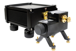
Figure 6 Integrated Doppler radar target simulator.
Preconfigured Doppler target simulators are also available, such as Eravant model STR-793-12-D1 which operates from 77 to 81 GHz (see Figure 6). It includes a direct-read attenuator and a WR-12 interface for connection to a user-specified antenna. Carrier and sideband suppression are 30 dB and 20 dB, respectively. Doppler frequencies up to 250 MHz are supported. The realized RCS depends on the antenna used and any additional insertion loss if a connecting cable is used.
For an unmodulated (CW) Doppler radar system, the distance to the target is ambiguous. Adjustment of the return signal amplitude may be interpreted as either a change in RCS or a change in distance from the radar system. For an FMCW or pulsed radar system, the distance to the target is generally determined by evaluating the effects of signal delay. For these systems valid interpretations of a change in signal level, when everything else is held constant, include a change in the RCS, a change in the target’s position in the radar beam or a change in the propagation loss.
CONCLUSION
A directional antenna that is intentionally mismatched can be used as a simulated radar target. The expected RCS of the target can be estimated from the antenna gain. By controlling the mount of received power that is reflected back to the antenna, the RCS of the target can be varied. Separate antennas may be used for receiving and retransmitting the received signal to achieve more flexibility in the polarization response.
By frequency-shifting the received radar signal using a SSB modulator, and retransmitting the frequency-shifted signal back to the radar system, it is possible to effectively simulate a moving target using stationary equipment. A variety of configurations are possible using either one or two antennas. A low-cost single-antenna system that includes only a signal diplexer, a SSB modulator and an adjustable attenuator can be used to measure the effective range of Doppler radar heads in a production environment or when servicing radar systems in the field.
References
- S. D. Robertson, “Targets for Microwave Radar Navigation,” Bell System Technical Journal, Vol. 26, No. 4, October 1947, pp 852–869.
- R. L. Brandenburg, A Deception Repeater for Conical-Scan Automatic Tracking Radars, Naval Research Lab, 1956.
- P. Rippl, J. Iberle, P. A. Scharf and T. Walter, “Radar Scenario Generation for Automotive Applications in the E Band,” IEEE Journal of Microwaves, Vol. 2, No. 2, April 2022, pp. 253–261.
- G. Körner, M. Hoffmann, S. Neidhardt, M. Beer, C. Carlowitz and M. Vossiek, “Multirate Universal Radar Target Simulator for an Accurate Moving Target Simulation,” IEEE Transactions on Microwave Theory and Techniques, Vol. 69, No. 5, May 2021, pp. 2730–2740.
- S. Shahir, M. -R. Nezhad-Ahmadi, M. Chavoshi and G. Rafi, “Millimeter-Wave Automotive Radar Characterization and Target Simulator Systems,” IEEE International Symposium on Antennas and Propagation and USNC-URSI Radio Science Meeting, July 2019.
- W. Scheiblhofer, R. Feger, A. Haderer and A. Stelzer, “Low-Cost Target Simulator for End-of-Line Tests of 24-GHz Radar Sensors,” 22nd International Microwave and Radar Conference, May 2018.
- H. T. Friis, “A Note on a Simple Transmission Formula,” Proceedings of the IRE, Vol. 34, No. 5, May 1946, pp. 254–256.
- M. Skolnik, Radar Handbook, McGraw-Hill, Inc., 1990.
- “RF & Microwave Fiber Optic Delay Line System,” EMCORE, January 2022, Web, https://emcore.com/wp-content/uploads/2022/02/RF-MW-Delay-Lines-System.pdf.