

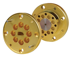
Figure 1 Uni-Guide waveguide connector.
Hermetically sealed electronic packages with waveguide interfaces can be challenging to design and costly to produce. Direct transitions from a microstrip circuit to a standard waveguide typically require a sealed dielectric window embedded in the waveguide channel. A common alternative with fewer design and manufacturing challenges uses a coaxial glass bead embedded in the package wall. The outside end of the bead’s center conductor is mated with a coaxial bulkhead connector, and a separate coaxial-to-waveguide adapter is added to complete the hermetically sealed waveguide interface.
Eravant’s Uni-Guide™ waveguide connectors introduce a combined packaging approach, as seen in Figure 1. Several standard models provide full waveguide band coverage, with rectangular waveguide sizes ranging from WR-42 (18 to 26.5 GHz) through WR-10 (75 to 110 GHz). By sharing the same electrical and mechanical interfaces used by standard coaxial connectors, Uni-Guide connectors enable more direct transitions from microstrip circuits to waveguide ports, while taking advantage of the relative simplicity and low cost of a glass bead embedded in the electronic package. Depending on the Uni-Guide model, the angular orientation of the waveguide interface can be rotated in increments of either 45 or 90 degrees. Field-replaceable and field-configurable Uni-Guide connectors can reduce the costs and delays associated with component design and production. They also provide a means of repairing and maintaining equipment that requires frequent waveguide connections. Common applications include antenna test ranges, portable test equipment and production test stations. Many common waveguide components such as amplifiers, mixers, frequency multipliers and noise sources, can also benefit from the versatility and effectiveness of Uni-Guide connectors.

Figure 2 Design concept of waveguide and coax connector interface.
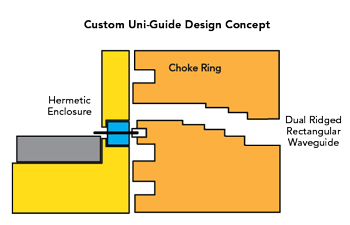
Figure 3 Removal of back-short usually included in design.
The design concept behind Uni-Guide connectors is a waveguide interface that matches that of a standard coaxial connector, as demonstrated in Figure 2. The pin protruding from a coaxial glass seal passes through a small hole in the waveguide connector and terminates inside a receptacle embedded in the mode transition section of the connector assembly. An impedance transformer bridges the span between the mode transition and the waveguide flange. Hole patterns in the waveguide connector match those of a standard coaxial connector, making Uni-Guide waveguide connectors fully interchangeable with industry-standard coaxial connectors. By avoiding a pair of mated coaxial connectors in the signal path, Uni-Guide connectors achieve lower insertion loss and improved impedance matching when compared to other realizations.
Standard Uni-Guide waveguide connectors include model SUF-1009-280-S1, spanning 75 to 100 GHz with a WR-10 waveguide flange. Its coaxial port is compatible with 1 mm flanged connectors that accept a pin diameter of 9 mils and mounting holes separated by 0.28 in. Other Uni-Guide connectors with the same 1 mm coaxial interface use WR-12 and WR-15 flanges. Additionally, Eravant offers models that interface to waveguide sizes WR-19, WR-22 and WR-28, covering full waveguide bands from 24 to 60 GHz. These models are compatible with 1.85 mm flanged coaxial connectors that accept a pin diameter of 12 mils and have mounting holes spaced 0.48 in. apart.
Additional Uni-Guide models include one that operates from 18 to 28 GHz using a WR-42 waveguide interface, and another that covers 22 to 33 GHz through a WR-34 flange. Both models accept a pin diameter of 12 mils and require mounting holes spaced 0.750 in. apart on either side of the glass bead. To accommodate standard coaxial connector types, an additional pair of mounting holes may be added to the component package to make these waveguide connectors fully interchangeable with commonly available coaxial connectors.
CUSTOM DESIGN EXAMPLES
A customer who recognized the benefits of field-replaceable and field-configurable waveguide ports presented a set of unique requirements. Their needs were not fully addressed by any standard Uni-Guide connector. In particular, the customer required a WRD-180 dual-ridged waveguide interface that covers 18 to 40 GHz with a maximum insertion loss of 0.25 dB and a minimum return loss of 15 dB. For comparison, the standard Uni-Guide connector model SUF-2812-480-S1 provides an insertion loss of 0.3 dB and a return loss of 20 dB from 24 to 44 GHz.
Figure 4 Split block connector design.
Eravant engineers were confident they could modify the mode transition and impedance transformer of a standard Uni-Guide connector to achieve the wider bandwidth of a WRD-180 waveguide interface. However, the customer also presented an existing, non-standard coaxial interface that could not be modified. The greatest challenge was a glass seal with a center pin that was shorter than what a standard Uni-Guide connector requires. The shorter pin forced the removal of the back-short typically included with a standard connector design, as seen in Figure 3. Because a back-short is essential for impedance matching and mode conversion, the component package’s outer surface would have to serve as the back-short in the new design. The proposed arrangement increased the risk of signal leakage and spurious resonances caused by small gaps between the package and the waveguide connector. As a result, a choke ring was included in the proposed design to reduce signal leakage and suppress resonances.
To demonstrate feasibility and optimize the dimensions of the mode converter and impedance transformer, electromagnetic simulations were performed using CST Studio. The optimized design predicted a minimum return loss of 20 dB from 18 to 40 GHz. The base material selected for the custom connector is 6061-T651 aluminum, with silver plating to minimize losses. Designed to accept pin lengths from 0.044 to 0.060 in., a pressed-in receptacle was fabricated from beryllium copper and plated with a hard gold alloy. The custom design uses a split block construction approach to accommodate the greater complexity of the design. The split block also enables the use of economical fabrication methods while supporting a straightforward assembly process, as seen in Figure 4.
CONNECTOR TESTING
Measurements of the connector’s insertion loss and return loss faced the same challenges presented by any adapter that couples one connector type to another. Usually, two identical adapters are connected back-to-back and measured as a combined assembly. The performance of one adapter is determined from measurements of the combined adapters. This approach is commonly used to test coaxial adapters, coaxial to waveguide transitions and waveguide mode converters.
Two of the custom WRD-180 connectors were connected at their waveguide ports, with their combined electrical response measured at their coaxial ports. Due to their lack of an integrated back-short, the waveguide connectors could not accept a standard coaxial connector at their coaxial ports. A pair of cylindrical test fixture pieces was fabricated, with the ends of each piece accommodating either a 2.92 mm coaxial connector or the coaxial interface of a WRD-180 waveguide connector, as seen in Figure 5. A hole passing through each fixture piece provided a coaxial transmission path between the custom waveguide connector and the coaxial connector. A Teflon sleeve served as a dielectric insulator for the connecting coaxial line. The insertion loss of each center piece was estimated as approximately 0.2 dB. The insertion loss of the two coaxial connectors was measured separately.
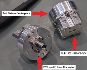
Figure 5 Test fixture for Uni-Guide connectors.
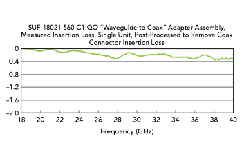
Figure 6 Insertion loss of a single waveguide connector.
The waveguide connectors were clamped together during back-to-back measurements to determine their combined insertion loss and return loss. Insertion loss for a single connector was estimated to be one-half of the measured attenuation. This approximation assumes that mismatch effects have a negligible impact on overall insertion loss. The attenuation of the fixture center pieces and the 2.92 mm coaxial connectors were subtracted from the measured insertion loss to yield the insertion loss of a single waveguide connector, as shown in Figure 6.
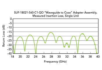
Figure 7 The estimated return loss of a single waveguide connector.
The return loss of the combined assembly was also measured. Noting that mismatch effects are additive for low loss pairs of identical components connected back-to-back, the estimated return loss of a single waveguide connector was estimated as the return loss of the combined connectors, offset by 4 dB to compensate for the additive effects of cascaded components, as demonstrated in Figure 7.
Overall, the first iteration of the custom design nearly meets all requirements presented by the customer. Electromagnetic simulations predicted that the custom connectors would handle at least 200 W. Although the measured insertion loss of 0.4 dB (average) exceeded the desired goal of 0.25 dB, return loss met or exceeded the goal of 15 dB. The connectors thus demonstrated the feasibility and practicality of expanding the Uni-Guide product family to include dual-ridged waveguide interfaces.
Based on the success of the WRD-180 design, another Uni-Guide waveguide connector was developed for the same customer to cover frequencies from 6 to 18 GHz using a WRD-650 waveguide interface. This custom design was not required to mate with an unusually short center pin, to allow the use of an integrated back-short similar to those used in standard Uni-Guide connectors. The WRD-650 Uni-Guide connector accepts a standard 36-mil pin and supports power levels up to 400 W. Maximum insertion loss is 0.3 dB and minimum return loss is 15 dB from 6.5 to 18 GHz.
By using Uni-Guide waveguide connectors, component manufacturers can offer a wide range of waveguide sizes and orientations using a reduced number of package designs. As drop-in replacements for existing industry-standard coaxial connectors, they are field-replaceable and field-configurable. When customers require a specific waveguide size and orientation on an electronic component, Uni-Guide waveguide connectors reduce or eliminate the need for non-recurring engineering and its associated dual costs and delays. Custom designs utilizing dual-ridge rectangular waveguides have been developed, with more designs and new applications on the horizon.
Eravant applies design modifications to standard components and develops integrated assemblies for specific applications. They typically have turnaround times from two days to eight weeks for complex assemblies. Custom solutions are based on a design library of over 5,000 components. Using mature designs as a foundation not only reduces uncertainty but also ensures that design reviews are completed faster and hardware is manufactured sooner. Eravant works closely with customers through an interactive development process that makes prototypes more compact, robust and affordable with each new revision.