
Modern communication systems often require narrow band filters presenting high selectivity and low insertion loss. When there are also stringent requirements on the overall dimensions of the filtering structure, it could become very problematic to select a suitable class of resonators having at the same time compactness and large values of the unloaded quality factor (Q0). A possible way to reduce losses using low Q0 resonators is to limit the filter order (that is, the number of resonators) looking for suitable design techniques that allow the selectivity to be concentrated in frequency intervals as narrow as possible (transmission zeros realized with cross couplings are one example of this approach).
However, there are applications where the use of classical bandpass filters does not produce the maximum possible attenuation (for a given number of resonators). As an example, consider the duplexers used for connecting a single antenna to transmitter (TX) and receiver (RX) units. The task of the two filters is to achieve high selectivity in frequency bands of limited extension (the RX filter must reject the TX band and the TX filter must reject the RX band). Using classical bandpass filters (even with suitably located transmission zeros) many resonators could be required, thus precluding the possibility of using low unloaded Q resonators (such as those realizable in microstrip, which, on the other hand, would allow very compact dimensions). Recently, design procedures for single-sided filters have been repeated in the literature1-4that satisfy the requirements in one passband and one stopband, both of finite extension. For a given selectivity mask, these filters require a smaller number of resonators with respect to classical bandpass filters and are particularly suited to achieve both high selectivity and low loss.
This article presents a design approach for single-sided filters and duplexers in microstrip. The filters are characterized by a quasi-equiripple response both in the passband and in the stopband (transmission zeros are suitably introduced in the stopband in order to improve selectivity and further reduce the number of resonators for a given selectivity). The novel filter configuration has been verified through the design (using a suitable procedure) and the fabrication of a microstrip duplexer operating in two mobile communications bands composed of two single-sided filters. The results obtained are presented and discussed.
Synthesis of Idealized Single-sided Filters
It is assumed that the single-sided filters considered here can be represented by the usual equivalent network shown in Figure 1 , where n shunt resonators are cascaded through n+1 ideal admittance inverters.
The admittance inverter parameters Ji,i+1 are equal to JR but for n odd, while for n even Jn/2,n/2+1 is given by Jn/2,n/2+1 =[{ 2+1}1/2 ± ]JR (with the minus sign for n = 4,8,12... and the plus sign for n = 2,6,10...) where e is defined by the maximum attenuation in the filter passband, Am = 10log(1 + 2, and JR is an arbitrary reference admittance. The resonator's susceptance Bk of the k-th resonator is assumed to have the frequency dependence:

where
f = frequency variable
Ak, fpk and fsk = parameters independent of f
which completely characterize the susceptance Bk(f).
A synthesis procedure has been developed, which determines the coefficients Ak, fpk and fsk once the single-sided filter specifications are given (that is, the initial and final frequencies of passband (fpa, fpb) and stopband (fsa, fsb), the number n of resonators and the required passband return loss). This procedure, originally derived for the synthesis of rectangular waveguide single-sided filters,2 allows a quasi-equiripple response to be obtained both in the passband and stopband, and can be very easily implemented because only the Chebycheff low pass prototype parameters gn are required. The procedure has been suitably modified in order to be applicable to the structure considered here and is described in Appendix A .
Distributed Implementation of Single-sided Resonators
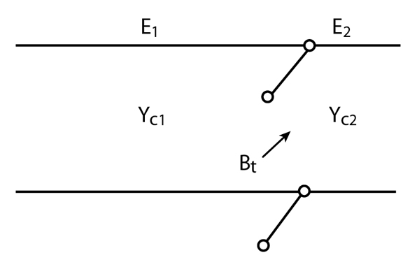
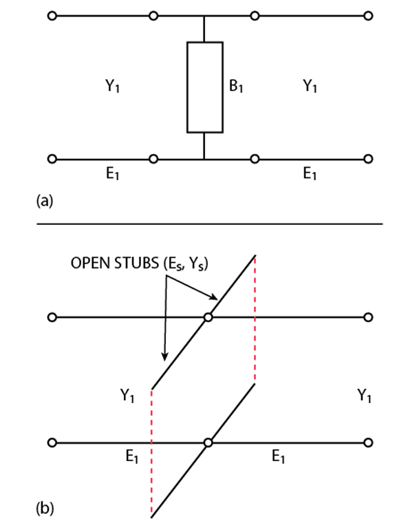
For implementing single-sided filters as a microstrip circuit, a distributed resonator must be identified which approximates the required frequency behavior of the susceptance B, as given by Equation 1. It can be easily verified that the simple network of Figure 2 presents a pole-zero pair in Bt, which is the first condition required for distributed resonators.
Let E1 and E2 be the electrical lengths of the two open stubs at frequencies fsk and fpk, respectively, that is

where
l1 and l2 = physical length of the two stubs
 = velocity of the propagation
In order to obtain the pole-zero pair in Bt at the frequencies fsk and fpk, the lengths E1 and E2 must be given by

with
Note that fpk can be greater or lower than fsk, always resulting in admissible values for E2.
For determining the admittance Yc1 (for a given value of  ), the frequency derivative of Bt at fpk must be equal to that computed from Equation 1; the following expression is then obtained
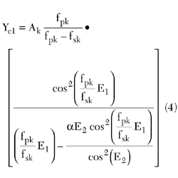
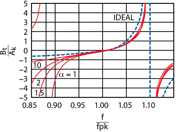
The parameter represents a degree of freedom in the resonator dimensioning that can be used for improving the accuracy of the frequency approximation. In fact, it should be observed that the considered distributed network actually presents two poles in the susceptance on both sides of the zero, about at the same absolute distance for Yc1 = Yc2( = 1). Using the parameter , the undesired zero can be moved away, improving the overall approximation. As an example, Figure 3 shows the frequency variation of Bt/Ak for some values of a and with fsk/fpk = 1.1.
It can be observed that, as a is increased, the approximation to the ideal susceptance is improved, especially around fpk. However, for frequencies close to fsk, the approximation is not very good, so the frequency behavior of single-sided filters using this type of resonator could be rather distorted in the stopband.
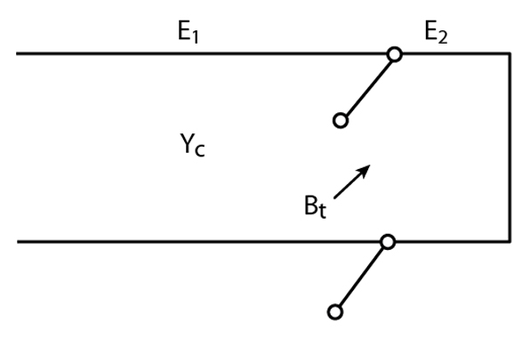
A second type of distributed resonator that approximates the ideal susceptance (Equation 1) is reported in Figure 4 ; this network allows placing the pole only at frequencies greater than the zero (the previous resonator allowed fsk/fpk to be either lower or greater than 1).
The main advantage of this resonator is a better approximation of the ideal response being the second pole of the network at frequencies much higher than fsk. Figure 5 shows the normalized susceptance Bt/Ak obtained for fsk/fpk = 1.1 and = 1. In this case the approximation obtained is much more satisfactory than with the previous resonator.
For determining the parameters of this resonator, the same conditions imposed for the previous one can be used. The following relationships are then derived

Note, in this case it has been assumed Yc1 = Yc2 = Yc (that is, = 1).

Design Guidelines for Single-sided Filters
Choice of Resonator Parameters
To design the single-sided filter, the reference impedance ZR = 1/JR must be first selected. Its value determines the level of all the admittances in the filter and is a determinant for the physical feasibility of the final microstrip structure. In order to allow a suitable selection for this parameter, its influence on the maximum and minimum levels of the various microstrip lines characteristic impedances obtained from a design must be considered. Another design parameter determining the feasibility of the filter is the transition bandwidth Bt for a given passband and stopband extension. In fact, as Btdecreases, the maximum value required for the resonator's characteristic impedance becomes larger (it has been found that a value of the normalized transition bandwidth Btn = Bt/f0 of about 0.5 represents the limit for practical realization's with both types of resonators).
Moreover, when the first resonator type is used, it could be necessary to obtain a realizable filter to vary the value of from resonator to resonator. It has also been found that smaller values of Btncan be allowed when the normalized pass- and stopbands Bpn and Bsndecrease with respect to Btn.
Once a value for ZR has been selected, the two external admittance inverters can be determined as

In the case of a sufficiently large transition bandwidth, Z0/ZR = 1. In this way the two external inverters are no longer necessary.
Admittance Inverter Realization
The simplest way to approximate an ideal inverter JR is to use a  0/4 transmission line section of characteristic impedance Zc = 1/JR. However, this solution may have two drawbacks. First, in some cases, the characteristic impedance to be realized is too small (or too high) for a practical implementation. Second, in some cases, the overall size of the filter could be unacceptable. Another well-known equivalent circuit for the ideal inverter is shown in Figure 6 .
For a given value of JR, the parameters of the equivalent circuit must satisfy the relations

It is then possible to assign arbitrarily a value to the characteristic admittance of the two line sections. Two open stubs in parallel of characteristic admittance Ys = BI/2tan(Es) can be used for realizing the susceptance B. It should be observed that the overall electrical length of the circuit is less than  /2 only for YI < JR. This means that the characteristic impedance of the lines implementing the inverters must be always larger than the reference impedance ZR = 1/JR. Note that, once EI is obtained, the geometrical length of the line sections is typically computed at the center frequency of the filter passband. Finally, when this circuit is used for implementing the inverters, a frequency variation of the inverter's parameter is introduced, which generally results in a distortion of the filter passband.
|
Table 1 | ||
|
|
Filter A |
Filter B |
|
Passband (GHz) |
1.800 to 1.880 |
2.095 to 2.175 |
|
Stopband (GHz) |
2.105 to 2.240 |
1.760 to 1.880 |
|
Number of resonators |
2 |
2 |
|
Return loss (dB) |
26 |
26 |

Duplexer Realization with Single-sided Filters
Duplexers are often used for separating different frequency bands coming from a receiving antenna. In this case the simple scheme shown in Figure 7 is generally adopted.5
The task of the two transmission line sections is to present an open circuit at the center passband frequency of the opposite filter (so their length is approximately a quarter wavelength at these frequencies). Moreover, the selectivity requirements for this class of duplexers are often specified only in the passband of the two filters (each filter must provide a prescribed attenuation only in the passband of the other filter). When duplexers are realized in planar technology (microstrip), the use of single-sided filters is very convenient, because high attenuation can be obtained with few resonators, allowing low insertion losses even with a passband of a few percent. In order to validate these assumptions, a test duplexer having the specifications listed in Table 1 has been designed using single-sided filters.
Filter A has been implemented with resonators of the second type, while filter B is of the first type. The inverters use the two open stubs topology, with a reference impedance ZR=50  (in this way the terminal inverters are not required). Since the number of resonators is even, the actual value of the inner inverter parameter is given by JR = [{ 2 + 1}1/2 + e ]/ZR. The parameters obtained from the synthesis of the two filters are reported in Table 2 , together with the electrical lengths EA, EB of the two line sections.
|
Table 2 | ||
|
|
Filter A |
Filter B |
|
fpk (GHz) |
1.844, 1.843 |
2.1297, 2.1290 |
|
Fsk(GHz) |
2.117, 2.193 |
1.7800, 1.8675 |
|
Zck ( |
100.2, 66.37 |
63.56, 101.50 |
|
E1k |
90°, 90° |
90°, 90° |
|
E2k |
11.61°, 14.34° |
68.27°, 65.59° |
|
|
- |
1.27, 2.03 |
|
ZI ( |
83 |
99 |
|
ZS ( |
106 |
75 |
|
EI |
30.08° (at 1.82 GHz) |
25.69° (at 2.13 GHz) |
|
ES |
36.22° (at 1.82 GHz) |
31.19° (at 2.13 GHz) |
|
EA,B |
93.6° (at 2.13 GHz) |
91.2° (at 1.82 GHz) |
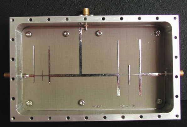
The duplexer has been fabricated in standard PCB technology, using a teflon substrate with the following parameters: = 2.55; dielectric thickness = 0.8 µm; metal thickness = 35 µm; tan  = 10-3. The effect of the various junctions and discontinuities has been taken into account by optimizing the microstrip lengths obtained from the initial design (Table 2) in a circuit simulator (MWOffice®). Figure 8 is a photograph of the fabricated prototype, while Figure 9 shows a comparison between the measurements and simulations.
First, it must be noted that no experimental adjustment as been performed on the prototype. The measured passbands are slightly displaced to lower frequencies with respect to the simulations (note that the return loss level is satisfactory for a practical realization, even if it is lower than expected). The passband's displacement is probably due to inaccuracies either in the fabrication process or in the simulation of discontinuities (it could easily be corrected with a few experimental adjustments of the stub's length).
However, the most interesting result concerns the two stopbands - both present the expected level of attenuation (approximately 50 dB). Note that this result has been obtained with only two resonators in each filter. Also, the passband attenuation is very good. The measured value at the center passband is approximately 0.5 dB and remains below 0.85 dB at the passband edges.

Conclusion
A new class of microstrip, high selectivity bandpass filters has been introduced that allows realizing large values of attenuation in a single stopband with a very low insertion loss in the passband. Possible topologies of resonators for this type of filter have been studied, deriving useful design guides for their dimensioning.
The realization of duplexers being a convenient use of the novel class of filters introduced, the design and fabrication of a microstrip duplexer prototype operating in mobile communications bands have been performed. The results obtained have confirmed the expected behavior for the novel class of microstrip filters presented.
References
1. H.C. Bell, "Single-passband, Single-stopband Narrow Band Filters," IEEE International Microwave Symposium Digest , Vol. 2, No. 6, June 2000, pp. 1657-1659.
2. S. Cavalieri D'Oro and G. Macchiarella, "Design of Asymmetric Filters with Requirements in Two Bands of Finite Extension," IEEE Transactions on Microwave Theory and Techniques , Vol. 40, No. 6, June 2001, pp. 1045-1049.
3. G. Macchiarella and A. Bovatti, "Single-sided Filters in Microstrip Technology," 31st European Microwave Conference, London, England, September 2001.
4. G. Macchiarella and A. Bovatti, "Design of Microstrip Duplexers for Mobile Communications Using Single-sided Filters Technology," 32nd European Microwave Conference, Milan, Italy, October 2002.
5. A. Morini and T. Rozzi, "Constraints to the Optimum Performance and Bandwidth Limitations of Diplexers Employing Symmetric Three-port Junctions," IEEE Transactions on Microwave Theory and Techniques , Vol. 44, No. 2, February 1996, pp. 242-248.
6. G.L. Matthaei, L. Yuong and E.M.T. Jones, "Microwave Filters, Impedance Matching Networks and Coupling Structures," McGraw Hill, New York, NY 1964.
 Giuseppe Macchiarella received his Laurea degree in electronic engineering from Politecnico di Milano, Italy, in 1975. From 1977 to 1987, he was with Centro Studi per le Telecomunicazioni Spaziali of the National Research Council of Italy (CNR), where he was involved in microwave propagation studies. In 1987, he became associate professor at Politecnico di Milano, where he currently teaches courses in electronics and microwaves. His research interests are in the field of microwave circuits, with special emphasis on microwave filters synthesis.
 Alberto Bovatti received his degree in telecomunication engineering from Politecnico di Milano, Italy, in 2001. He currently works for Forem S.r.l., where he is an RF design engineer specializing in low noise amplifiers and microstrip passive structures (filters, power splitters and hybrids).
|
Appendix A Synthesis of Single-sided Filters It is assumed that the filter network considered here has the topology shown in Figure 1, with the resonators exhibiting the frequency dependence given by Equation 1 (where f is the actual frequency domain considered in the filter response). It is also assumed that the filter specifications are given by the mask shown in Figure 1A .
If an equiripple response is imposed both in the passband and in the stopband, a suitable placement of the resonators poles is required. However, assume initially that fpk and fskare not depending on k, so that only two frequencies - fp and fs - specify the susceptance zero and pole for all the resonators. If a suitable frequency transformation is found, the normalized susceptance b'k = Bk/YR of each resonator can be derived from a standard low pass prototype filter (that is defined once the number n of the resonators and the maximum bandpass attenuation A1m are given):
where a'k = A'k/YR The parameters gk are the coefficients of the all-poles low pass prototype,6 here assumed to be of the Chebycheff kind. A suitable normalized radian frequency
The constants fp and fsdefine the frequency transformation. By requiring the equivalence, in the normalized frequency domain, of the passband extreme frequencies fpa and fpb two constraints are imposed on Equation 3A
From Equations 3A and 4A, the following expressions for fp and fs can be derived:
where
The constants a'k determine the values of the susceptances according to Equation 2A and, assuming
The overall filter, obtained according to the general configuration once all the susceptances b'k have been determined through the above formulas, will show an equiripple response in the passband (that is between fpa and fpb). Moreover n coincident transmission zeros will be obtained at the frequency fs in the stopband. The frequencies fsk between fsa and fsb must now be suitably distributed if an equiripple response is desired also in the stopband. Note that the reflection zeros in the passband are given by
with
A possible choice for the transmission zeros fsk is to distribute them in the stopband as the reflection zeros are distributed in the passband. This is obtained by exchanging fp and fs, fpa and fsa in Equation 7A.
where
Obviously, now having different fsk for each resonator, the frequency transformation (Equation 3A) will no longer be strictly meaningful. However, new expressions for a'k and fpk may be suitably derived by requiring two conditions on the passband response of the filter to be satisfied by each resonator. It has been found that a response very close to the original equiripple is obtained in the passband if the conservation of the susceptance b'k (as given by Equation 2A) is imposed at the frequencies f01 and f0n of the first and last zeros of the filter (given by Equation 7A, with k = 1 and k = n); then the final expressions for Ak and fpk, to be used in Equation 1 together with fsk from Equation 8A, will be given by
where
The above equations allow the definition of the single-sided filter in its general configuration, with a quasi-equiripple response both in pass- and stopbands. |


 ' satisfying the above relationship may be


