
Advances in MIC and MMIC technology have motivated the demand for compact, high performance filters, diplexers and multiplexers used in microwave receiver systems. Combline bandpass filters have been in great demand because of their structural compactness and excellent wide stop-band performance. They are easy to fabricate in printed circuit form and are mostly used in a crowded frequency spectrum. There are two versions of combline filters - conventional transformer input, and tapped lines input and output. The tapped combline filter offers space and cost saving advantages over the conventional filter because the first and last end-sections of the filters are eliminated. This filter version is also attractive because the parallel coupling at the transformer sections become physically unrealizable.
Combline filters have been previously described by several authors.1-6 The advantages of a combline filter with tapped line input over the conventional filter input have been detailed by Dishal,7 who described the method for tapped interdigital filter design over a narrow bandwidth. Crystal3 proposed an exact open wire line equivalent for the tapped line input stage and established an equivalence between the transformer input and the tapped line input coupling circuit. Shortcomings of this method include the impossibility of an exact equivalence over a broad frequency band and that graphical rather than analytical expressions are provided. Caspi and Adelman5 suggested another open wire line equivalent circuit based on Crystal3, and published an analytical expression valid up to 15 percent bandwidth for a combline filter with tapped input and output.
Unfortunately, an accurate design of the combline filter is not simple and the techniques available are not directly applicable to microstrip or suspended substrate stripline (SSS). This article presents the design of a quasi-planar combline filter using multicoupled suspended substrate striplines. The suspended substrate medium is considered an appropriate choice for printed circuit filters because it yields higher Qs (quality factor) than similar microstrip and stripline. This is because most of the electric field occurs in air and, therefore, results in lower loss filters with sharper band edges. The temperature characteristics in suspended substrate medium are virtually independent of dielectric material variations for the reasons cited above.
Approximate Design
Combline filters can be designed using the method outlined by Capsi and Adelman5 for the tapped input and output, and G.L. Matthaei1 for a transformer input. Capsi and Adelman provide expressions in terms of self and mutual capacitance. It is more convenient to design the filter using the concept of even- and odd-mode impedances rather than self and mutual capacitance per unit length. The advantage of this approach lies in the relative simplicity of the design formulas applicable to filters and the availability of expressions for microstrip or suspended substrate stripline in terms of even- and odd-mode impedances. This approach offers easy amenability to computer-aided design.
Denig6 described the expressions in terms of even-mode impedance Zeven and odd-mode impedance Zodd. It is generally impossible to realize arbitrary even- and odd-mode impedances to design a filter. Two approaches can be adopted. In the present design, the same line width with varying strip spacing corresponding to the required Zeven and Zodd is used as necessitated by the desired filter specification. The use of equal resonator strip widths simplifies the design and analysis of the filters. The design begins with the selection of the admittance Ya of the resonator line, the center frequency and the electrical length  o. The electrical length can be selected as desired (shorter than
  /4). The resonator impedance is normally selected for a high Q factor of the resonator (approximately 76 Ω).
First, keeping the width of the resonators a constant, the strip spacings between the resonators8 are varied to obtain the required coupling coefficients from the calculated Zeven and Zodd for the desired filter bandwidth. Second, the tapping of the input and output 50 Ω lines at the first and last resonators generates an inductance at the end of the resonators which can be compensated by either a lumped capacitance equal to Cs5 or by an extension of the end resonators.4 The loading capacitance of the first and last resonators with tapping effect becomes Cs + Cmid. The loading capacitance of the internal resonators, Cmid, is given by

where
o = the electrical length of the resonator
 o = 2
o = 2 fo
fo
fo = the center frequency of the filter
The electrical length of the tapping point from the ground can be calculated from Caspi and Adelman.5
Simulation Technique
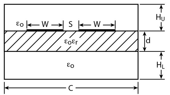
There are several specialized computer programs available to analyze multicoupled microstrip lines.9 However, there is no direct CAD program available for multicoupled suspended substrate stripline. Touchstone and Supercompact are generally restricted to the analysis of singly coupled SSS transmission sections. Modeling of the multiple coupled section with these CAD programs can be done based on Denig6 for the suspended substrate stripline shown in Figure 1 . This CAD program cannot take care of the coupling between non-adjacent resonators. Ignoring non-adjacent coupling results in some error, which becomes predominant in suspended substrate medium.
To account for the non-adjacent coupling between resonators and the composite effect of quasi-TEM modes, the [L], [C], [R] and [G] matrices per unit length for width and spacing corresponding to even- and odd-mode impedance for SSS are calculated using LINPAR software.10 With the help of these matrices, the filter response is calculated theoretically by using the software developed by Djordjevic.11
Realization Theory
With the conventional method, combline filters are realized as metal bar resonators. Conventional metal bar resonators can be visualized as an equivalent suspended substrate stripline resonator. Hence, the loading capacitors are replaced with metal-insulator-metal (MIM) printed capacitors. The proposed combline filter is realized using multicoupled suspended substrate striplines supporting quasi-TEM modes. The change in the design medium improves the loss characteristics of the filter, repeatability and realizability of printed circuit filters. Although the proposed quasi-planar circuit appears as a one-to-one replacement for the conventional metal bars circuit, it differs by one major guided-wave property because the quasi-planar realization supports N quasi-TEM modes in addition to all possible excitation of other higher order modes and the associated coupling between non-adjacent resonators. The software packages used10,11 are capable of accounting for the above two effects.
Filter Implementation
On the backside of the multicoupled suspended substrate stripline resonators, a toothed metallization pattern is printed well aligned under the corresponding resonators to form MIM capacitors. The width of metallization is made equal to the width of the resonator and length of the toothed metallization is calculated from

where
W = the width of the capacitor metallization
d = substrate thickness
 r = the dielectric constant
For realizing the actual metallization required for the capacitor, the fringing capacitance of the open-end resonator should be considered because it leads to shifting of the filter response towards a lower frequency. The shift in center frequency of the filter response is corrected by trimming the toothed metallization on the back of the substrate.

The tapping effect of the input and output 50  lines on the first and last resonators is compensated by increasing the corresponding resonator length by approximately 10 percent of the actual length of the resonator. An approximate five percent increase in length is usually required for the tapping effect, and the remaining five percent is usually trimmed off during adjustment. The lengthening of the first and last resonator is found to compensate for the effect of the physical tap point. This technique serves to obtain a correct length at the resonant frequency and experimentally correct the tap-point location. During each test, gradual trimming of the first and last resonators at their open end is required, until both input and output SWR have reached the optimum achievable equal ripple performance across the band. Adding small tuning stubs at the input and output 50 transmission lines also minimizes the input and output SWR.
The input and output 50 W transmission lines are printed on composite substrate microstrip lines. A slab of 6010.2 RT/Duroid with an r = 10.2 and a thickness of 0.635 mm is inserted beneath the filter substrate to reduce the width of the 50 transmission lines, which in turn reduces the width of T-junctions formed at the tapping positions.
Experimental Results
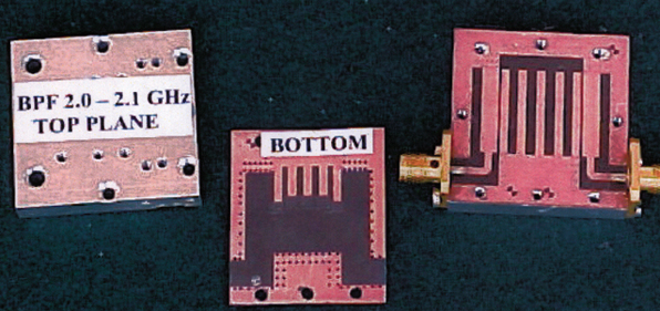
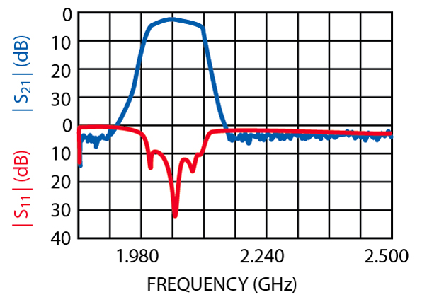
A five-pole filter with 100 MHz bandwidth, using a conventional transformer input, has been designed, fabricated and tested in the frequency range of 2.0 to 2.1 GHz. The circuit has been printed on a substrate with a dielectric constant r = 2.2, thickness d = 0.254 mm, a conductor thickness of 1/2 oz and with air-gaps Hl = Hu = 1.0 mm. The electrical length of the resonators is /8. The size of the filter is 34 x 35 mm. The 3 dB experimental bandwidth is observed to be approximately 100 MHz. A photograph of this filter is shown in Figure 2 . The measured insertion loss is approximately 2.71 dB at the center frequency and the rejection is 35 dB, 50 MHz away from the band edge (3 dB bandwidth points). The experimental results are shown in Figure 3 .

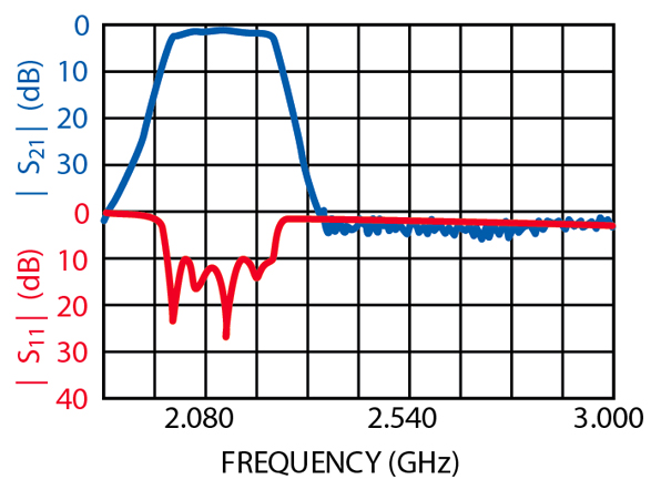
Two filters with pass bands of 2.00 to 2.25 GHz and 2.25 to 2.50 GHz (11.76 and 10.52 percent, respectively) have been designed, fabricated and tested with both transformers and tapped lines. The circuits have been printed on substrates with a dielectric constant r = 2.2 and a thickness d = 0.254 mm, a conductor thickness of 1/2 oz and air gaps H1 = Hu = 1.0 mm. The electrical size of the resonators is /8. The size of the filters with transformers is 30 x 35 mm. Figure 4 shows a photograph of the lower frequency device. Its insertion loss is 1.42 dB and its return loss is 10 dB over the pass band. The rejection is observed to be approximately 18 dB down, 50 MHz away from the band edges at the 3 dB points. The filter response is shown in Figure 5 . The higher frequency filter shows an insertion loss of 1.32 dB with a return loss of 10 dB over the pass band. The rejection is also 18 dB. Its response is shown in Figure 6 .
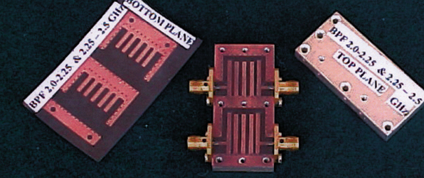
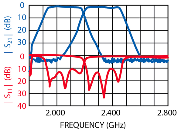
Both filters with tapped line input and output were fabricated on a single substrate with dimensions of 24 x 50 mm. A photograph of the devices is shown in Figure 7 . Their insertion losses are 1.12 and 1.30 dB, respectively. Their measured responses are shown in Figure 8 .
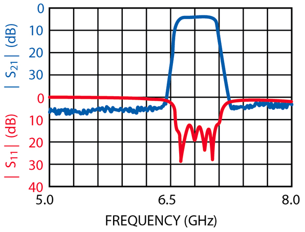
A filter with high selectivity having a 500 MHz bandwidth in the frequency range of 6.5 to 7.0 GHz (7.4 percent bandwidth) with tapped lines has been fabricated on a substrate of dielectric constant r = 2.2, a substrate thickness d = 0.254 mm, a conductor thickness 1/2 oz and with air-gaps Hl = 0.5 mm and Hu = 1.5 mm. The length of the resonators is 5.77 mm. The size of the filter is 30 x 20 mm. The insertion loss at the center frequency is less than 2.4 dB and the return loss over the bandwidth is better than 10 dB. The rejection of the filter is 13 dB, 50 MHz away from the band edges (3 dB bandwidth point). The 3 dB experimental bandwidth is observed to be approximately 500 MHz. A photograph and the experimental results of this filter are shown in Figures 9 and 10 , respectively.
Conclusion
Printed circuit combline bandpass filters have been designed and fabricated using multicoupled suspended substrate stripline and their performance evaluated for different bandwidths. It has been shown that the suspended substrate is the best choice for narrow bandpass applications. This is due to low losses (since most of the electric field is in air) and because of the good repeatability of printed circuits.
The proposed tapped line filter is shown to offer a promising reduction in size. It provides realizable dimensions in situations where a conventional filter has reached its physical limits. However, conventional filters are preferred over tapped line filters at higher frequencies with very narrow bandwidth because of inherent fabrication difficulties. For very narrow bandpass filters, the tapping point is very close to the shorted end of the resonator.

Acknowledgment
The authors wish to thank Shri N. Divakar, Sc. 'H' director, DLRL, Hyderabad, for allowing the use of the laboratory facility during the development.
The authors are also grateful to rear admiral A.K. Handa, VSM, director and dean, I.A.T., Pune, for permission to publish this work.
The authors are also thankful to Prof. V.A. Deshmukh, Sc. 'E' of I.A.T., Pune, and Mr. M.K. Das, Sc. 'E' of DLRL, Hyderabad, for their support and valuable suggestions.
References
1. G.L. Matthaei, "Combline Bandpass Filters of Narrow or Moderate Bandwidth," Microwave Journal , Vol. 6, No. 8, August 1963, pp. 82-91.
2. R.J. Wenzel, "Synthesis of Combline and Capacitivity Loaded Interdigital Bandpass Filters of Arbitrary Bandwidth," IEEE Transactions on Microwave Theory and Techniques , Vol. MTT-19, No. 8, August 1971, pp. 678-686.
3. E.G. Crystal, "Tapped Line Coupled Transmission Lines with Application to Interdigital and Combline Filters," IEEE Transactions on Microwave Theory and Techniques , Vol. MTT-23, No. 12, December 1975, pp. 1007-1012.
4. S. Wong, "Microstrip Tapped Line Filter Design," IEEE Transactions on Microwave Theory and Techniques , Vol. MTT-27, No. 1, January 1979, pp. 44-50.
5. S. Caspi and J. Adelman, "Design of Combline and Interdigital Filters with Tapped Line Input," IEEE Transactions on Microwave Theory and Techniques , Vol. 36, No. 4, April 1988, pp. 759-763.
6. C. Denig, "Using Microwave CAD Programs to Analyze Microstrip Interdigital Filters," Microwave Journal , Vol. 32, No. 3, March 1989, pp. 147-152.
7. M. Dishal, "A Simple Design Procedure for Small Percentage Bandwidth Round-rod Interdigital Filters," IEEE Transactions on Microwave Theory and Techniques , Vol. MTT-13, No. 9, September 1965, pp. 696-698.
8. J.I. Smith, "The Even- and Odd-mode Capacitance Parameters for Coupled Lines in Suspended Substrate," IEEE Transactions on Microwave Theory and Techniques , Vol. MTT-19, No. 5, May 1971, pp. 424-430.
9. R. Jansen and L. Wiemer, "Multiconductor for Hybrid Mode Approach for the Design of MIC Couplers and Lumped Elements Including Loss, Dispersion and Parasitics," European Microwave Conference Digest , 1984, pp. 430-435.
10. A.R. Djordjevic, et. al., "LINPAR for Windows," "Matrix Parameters for Multiconductor Transmission Lines," Software and User's Manual , Version 1.1, October 1989, Artech House Inc., Norwood, MA.
11. A.R. Djordjevic, et. al., "Scattering Parameters of Microwave Network with Multiconductor Transmission Line," Software and User's Manual , Version 1.0, 1995, Artech House Inc., Norwood, MA.
12. W.T. Lo and C.K.C. Tzuang, "K-band Quasi-planar Tapped Combline Filter and Diplexer," IEEE Transactions on Microwave Theory and Techniques , Vol. 41, No. 2, February 1993, pp. 215-223.