
Series- and parallel-combining of surface-mount capacitors is a standard approach to realize semi-arbitrary capacitance when designing a printed circuit board layout.
This pairing of components is often necessary as surface-mount parts are available in only a limited number of fixed values, such as 0.5, 1.0, 2.0 pF.
This article addresses some potential pitfalls that may arise in the form of unexpected resonance effects, brought about by the interaction of the paired parts and the complexity of their frequency behavior. The use of accurate computer-aided engineering (CAE) models to predict these effects is demonstrated.
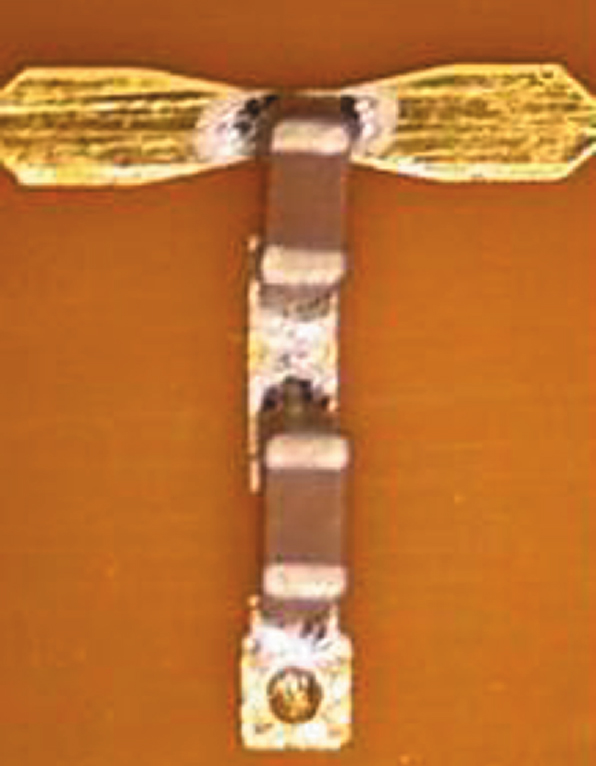
For the purposes of this analysis, a simplified series L-C equivalent circuit model (Figure 1) was used to extract an effective series inductance for each part, based on the measured first resonance:
The characteristics of the capacitors used in the study are listed in Table 1, as measured on 14 mil-thick FR4 using series, two-port, microstrip, test fixtures.
None of the capacitors exhibited secondary, higher order resonances below 15 GHz. The series L-C model is often used to represent capacitor performance, but it will become evident in the examples presented that models with greater physical representation are required for accurate performance prediction, even in simple, two-capacitor arrangements.
|
Table 1 | ||
|
Capacitance |
1st Series |
L eff |
|
0.5 |
14.5 |
0.24 |
|
0.7 |
11.2 |
0.29 |
|
1.2 |
8.7 |
0.27 |
|
1.5 |
8.0 |
0.26 |
|
3.3 |
5.1 |
0.30 |
|
6.8 |
3.2 |
0.36 |
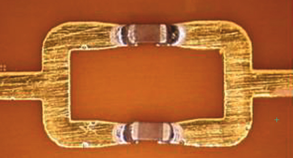
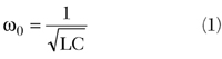
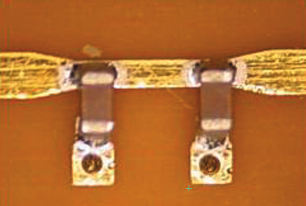
The three multiple-capacitor configurations considered here are the series-parallel (Figure 2), shunt-parallel (Figure 3) and shunt-series arrangements (Figure 4). Measured results for these configurations are analyzed below.
In each case, comparisons are made with accurate, substrate-scaleable capacitor models.1 The schematics used to generate the simulated results included a complete representation of the interconnect discontinuities.
Series-parallel Results
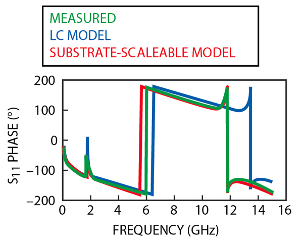
A comparison of the S11 magnitude and phase for a series-parallel combination of a 3.3 and 6.8 pF capacitor is shown in Figures 5 and 6, respectively.
In these graphs, the measured data is compared against the simulated results obtained using accurate, substrate-scaleable equivalent circuit models, and those from the simple L-C models. It is apparent that when paired together the series resonance of neither individual capacitor - which would manifest as a low S11 - is observed (5.1 and 3.2 GHz for the 3.3 and 6.8 pF capacitors, respectively, as listed in the table).
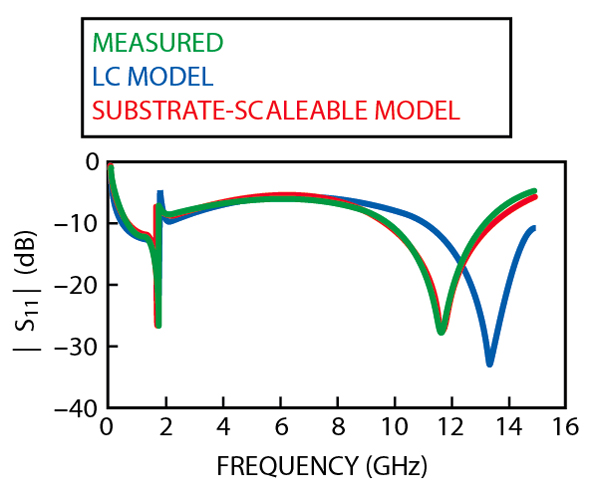
Furthermore, if one applies the simple L-C circuit model for each capacitor and combines the two in parallel, an effective capacitance of 10.1 pF is obtained with a net inductance of 0.17 nH.
From these values, a parallel resonance (minimum return loss or large S11) at 3.84 GHz is predicted, which is not evident in the data. On the contrary, a sharp series-parallel resonant frequency pair appears near 1.8 GHz, along with a strong series resonance at 11.8 GHz.
As noted above, the circuit schematics for the substrate-scaleable and simple L-C models both accounted for all discontinuity effects in the layout.
The low frequency correlation between the simulated and the measurement data argues the importance of proper interconnect modeling, as the resonant effects that would be expected from even the simple L-C model analysis are not observed via simulation.
The high frequency behavior points out the limitations of the simple L-C model, however, even when embedded within proper interconnect elements.
Shunt-parallel Results
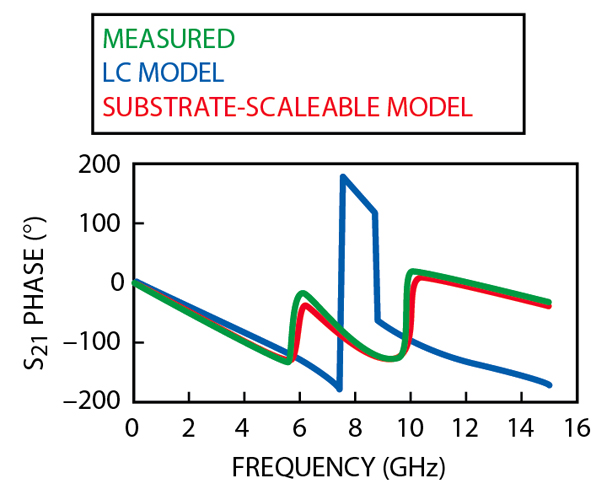
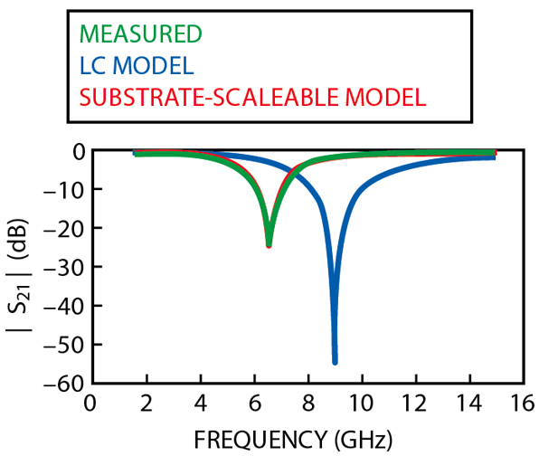
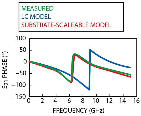
Measured data and simulation results of S21 for a shunt-parallel combination of a 0.5 and 1.5 pF capacitor are given in Figures 7 and 8. In the shunt configuration, the fundamental (series) resonance of the capacitors results in low impedance to ground and thus high insertion loss. The measured data show such effects at approximately 5.8 and 9.8 GHz, as do the simulated results using the substrate-scaleable model.
As an approximate analysis of this layout, each capacitor can be considered independently. Assuming the nominal capacitance value for each part, and attributing the low and high resonances individually to the 1.5 and 0.5 pF capacitor, respectively, an effective inductance of approximately 0.5 nH is extracted. Using the data in the table, it may be determined that each ground-via contributes an additional 0.25 nH inductance to the circuit.
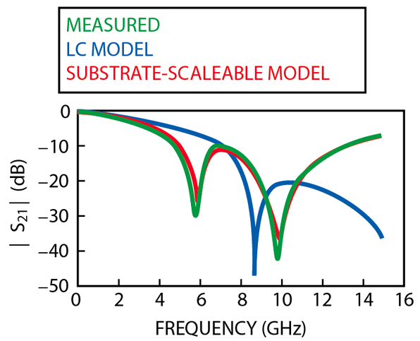
Thus, there is some consistency in treating the capacitors separately, since the analysis on each resonance yields approximately the same via inductance.
From a different perspective, one might consider first each capacitor in isolation (with its nominal capacitance and an overall inductance of 0.5 nH, after accounting for the via) and then evaluate the parallel combination of the two. This calculation leads to a net capacitance of 2.0 pF and an effective series inductance of 0.25 nH.
The corresponding resonant frequency is approximately 7.1 GHz, an effect that would lead to high insertion loss and one not noticeably present in the graphs. The simple L-C representation does, however, falsely predict a single resonance behavior (near 8.8 GHz).
Shunt-series Results
Finally, consider the shunt-series combination of a 0.7 and a 1.2 pF capacitor. Measured data and simulation results of S21 for this case are shown in Figures 9 and 10. As before, a preliminary analysis based on the simple series L-C model is used for each capacitor.
From the data in the table, along with the 0.25 nH via inductance determined above, the total inductance of the combined circuit is found to be 0.81 nH.
The effective capacitance of the series combination is 0.44 pF. This analysis leads to the prediction of a resonance at 8.4 GHz, whereas the measured results show it to occur at 6.5 GHz. It might be argued that the interconnect-line between the two capacitors introduces an additional inductance, tending to lower the resonant frequency.
While this is true to some extent, the overall inductance would have to be greater than 1.3 nH in order for the frequency to drop to 6.5 GHz (assuming the net capacitance remained at 0.44 pF).
It is unreasonable to assume that the short interconnect-line, which is less than 1 mm in length, adds more than 0.5 nH to the circuit.
As was found with the shunt-parallel circuit, simulated results using the simple L-C model, along with complete interconnect models, incorrectly predict the frequency response. The L-C model simulation indicates the resonance to occur very near to the frequency arrived at from the preliminary analysis (8.9 versus 8.4 GHz). Such a result may provide misplaced confidence in CAE simulation results.
Conclusion
A well-argued analysis, based on inadequate capacitor models, thus fails in varying degrees for the three examples described.
In each case the distributed effects of the interconnect-lines play a role in determining the frequency response. However, the most significant factor required in accurately predicting the circuit behavior is the capacitor model. The substrate-scaleable models provide nearly exact comparisons to the test results. Simplified L-C models, which might closely emulate measurement data from a series two-port test fixture, often prove to be inaccurate when used in common circuit configurations.
References
1. "Advanced Microwave Chip Capacitor Models," Microwave Journal , Vol. 45, No. 1, January 2002, pp. 190-192.
Tom Weller received his BS, MS and PhD degrees in electrical engineering from the University of Michigan in 1988, 1991 and 1995, respectively. He was a member of the technical staff at Hughes Space & Communications Group from 1988 to 1990. He is currently an associate professor in the department of electrical engineering at the University of South Florida (USF), and a member of the Wireless and Microwave (WAMI) Center. He co-founded Modelithics Inc. with Larry Dunleavy in 2001.
David Markell received his BS degree in electrical engineering from the University of South Florida (USF) in 1998, where he is currently pursuing his MSEE degree. He has worked at USF as a lead engineer of a research project designed to generate microwave substrate-scaleable SMT chip capacitor, resistor and inductor models for the completion of a CAE library for a major manufacturer. He is currently a member of the technical staff at Modelithics Inc.
John Capwell received his BS degree in electrical engineering from the University of South Florida (USF) in 1999, where he is currently pursuing his MS degree in electrical engineering. He is currently a member of the technical staff at Modelithics Inc.
Vicentiu (Vivi) Cojocaru received his MSc degree from Politehnica University in Bucharest, Romania, and his PhD degree from University College Dublin, Ireland. Between 1996 and 2000, he worked as a research scientist and as a lecturer in the department of electrical and electronic engineering at University College Dublin. He currently works as an engineering manager for TDK Electronics Ireland Ltd.