
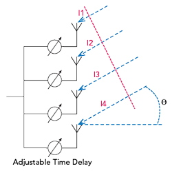
Figure 1 Four-element array and incoming plane wave.
Antenna arrays consisting of multiple radiating elements are widely used in both defense and commercial applications. The individual elements of the antenna array are usually fed with signals of different phases to form the desired radiation pattern, generally a beam or multiple beams. The beam can be steered by controlling the phase of the signals feeding each element, and the amplitudes of the signals are often optimized to minimize sidelobe radiation.
Cellular base stations widely use phase shifters to adjust the “down tilt” of the antenna, called remote electrical tilt (RET), which is used to optimize coverage and minimize interference. This enhances performance, such as increasing capacity, coverage and signal strength. The move toward sophisticated massive MIMO (mMIMO) solutions is an advanced form of beam steering, with the disadvantage that a separate radio is required for each antenna element. Yet significant performance gains can be made at much lower cost than mMIMO, using fewer transmitters and feeding the antenna elements with adjustable phase shifters. The growing momentum in spectrum rollout for the Citizens Broadband Radio Service (CBRS) for 4G and 5G networks will demand increasingly complex multi-array antennas with advanced beam steering to deliver the required quality of service and high data rates for cellular, enterprise and industrial IoT applications. As these applications are very cost sensitive, an adaptable beam former fed from a single transmitter offers significant value.
This article describes a beam steering antenna for the 3.6 GHz CBRS band using MEMS switches. The design supports high-power operation and uses delay lines configured in a patent-pending differential delay shifter (DDS). Although the common term for antenna beamformers is a “phase shifter,” the required network is actually a “delay shifter” to maintain the desired beam direction over a wide range of frequencies. Incorporating SP4T MEMS switches and delay lines with standard surface-mount packaging yields a highly compact and integrated form factor. This novel approach creates an all-electronic miniaturized delay shifter that can replace the large and bulky mechanical phase shifter components and motors often used for RET in traditional base station antennas. This all-electronic configuration allows for both horizontal and vertical antenna beam steering, with a significant improvement in switching speed and reliability compared to mechanical designs.
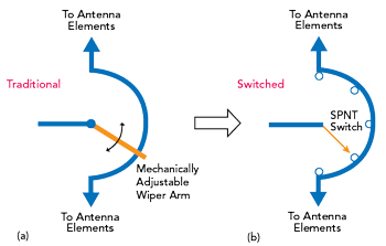
Figure 2 Traditional (a) and switched (b) phase shifters.
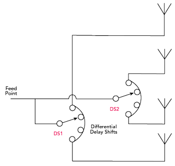
Figure 3 Two differential delay shifters feeding a four-element array.
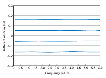
Figure 4 Four-step delay shifter differential delay vs. frequency.
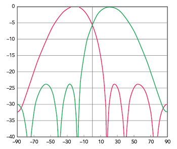
Figure 5 Simulated radiation pattern for two beam angles.
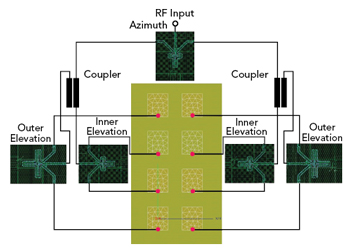
Figure 6 Feed network topology.
THEORY OF THE SWITCHED DDS
Consider a simple antenna array receiving a signal (see Figure 1). For a given angle of arrival, θ, the extra distance a signal travels to each element is l1, l2, l3 and l4, respectively. The time for the signal to travel these distances is independent of frequency and is simply a function of the element spacing, the angle of arrival and the propagation velocity, which is usually the speed of light in free space. By adjusting the time delay of each element’s feed for a given angle of arrival, the signals can be combined in phase at the common feed.
Although the time delay elements can be replaced with phase shifters, to ensure a constant beam angle versus frequency, the phase shifters must be adjusted for the specific frequency. This limits the operational bandwidth of the antenna; if the operating frequency is too far away from the design frequency, the direction of the antenna pattern will shift. If the angle, θ, is changed and the beam steered by rotating the incident plane around the center of the antenna, then any change in l1 is equal and opposite to the change in l4. Similarly, the changes in l2 and l3 are equal and opposite. By feeding pairs of elements symmetrically spaced around the center of the array with a differential delay shift network, these conditions are met.
In existing adjustable down tilt antennas for cellular base stations, this functionality is typically achieved using a mechanism controlled by a stepper or servo motor (see Figure 2a). The evolution from this conventional electromechanical phase shifter to a switched topology is shown in Figure 2b. Using discrete, quantized steps for the phase/delay adjustment eliminates the need for large mechanical movement, with more switching steps available to give finer resolution for more accurate beam steering applications. In both topologies, the single input is fed to two antenna elements with the appropriate impedance matching, since the two element impedances appear in parallel to the input. By adjusting the phase/delay, any length added into one path is equally subtracted from the other path, giving true differential phase control.
Figure 3 shows how two of these delay shifters with different transmission line lengths may be used to feed the simple four-element array shown in Figure 1. In this case, delay shift DS1 has 3x the delay variation as DS2, since the end elements are separated by 3x the unit element spacing. Although the schematic shows a direct feed to both delay shifters, an asymmetric power divider can be used to provide amplitude weighting or tapering of the individual elements.
3.6 GHz DDS DESIGN
A four-step DDS for the 3.6 GHz CBRS band was developed using the Menlo Micro MM5130 high-power SP4T switch. Using additional switches, this concept can be extended to eight or 16 delay steps. In this configuration, a key requirement for the switch is a series-only topology with very low parasitic capacitance for the off ports of the switch. This ensures low loss, wideband performance, as the effect of any parasitic capacitance is minimal.
Figure 4 shows the wideband performance of the four-step delay shifter used for the outer pair of elements shown in Figure 3. The maximum differential delay is approximately 0.16 ns, which corresponds to a propagation distance, d, of 50 mm. For an array with an element spacing, s, of 43 mm or λ/2 at 3.6 GHz, the beam steering angle is given by

where N is the number of elements between the two outputs of the delay shifter. In this case, N = 3, so the beam steering angle is 21 degrees. Figure 5 shows the simulated radiation patterns for the four-element array at ±21 degrees. The amplitude weights on the elements was adjusted to give sidelobe levels of -24 dB, a reasonable compromise between the main beamwidth and the sidelobes.
DELAY SHIFTER DESIGN
Practical design considerations were considered when selecting the number of elements for the array, with a 4 x 2 array the minimum number of elements to achieve the desired beam steering (see Figure 6). This array configuration requires three types of delay shifters: one for azimuth to switch the pattern among left, boresight and right and two types for elevation. The azimuth delay shift was configured to have three beam positions, -30, 0 and +30 degrees. This is enough for the relatively wide azimuth beam created by the two elements in each row of the array.