
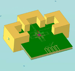
Figure 7 Keysight EMPro 3D model of the delay shifter.
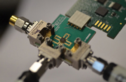
Figure 8 Testing the differential delay shifter prototype.
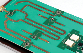
Figure 9 Feed network with three types of delay shifters.
The first elevation delay shifter controls the delay states between the two inner patch elements, while the second controls the delay state of the two outer patches. Since the distance between the two outer patch elements is 3x the distance between the two middle elements, the corresponding delay shifter was designed with 3x the delay shift. In total, the feed structure encompasses five delay shifters: one for azimuth, two inner pair and two outer pair for elevation. Since the selected switch is a SP4T configuration, the array design uses four delay states in the elevation/vertical plane. Four is not a hard limitation; it can be extended using higher throw switches or several switches in parallel.
The three different types of delay shifters were designed using Keysight ADS and verified and fine-tuned using Keysight EMPro. A multidimensional three-port S-parameter file was exported and used in the top-level simulation. A rendering of the outer pair delay shifter simulation model in Keysight EMPro is shown in Figure 7. Figure 8 shows the outer pair delay shifter being tested. The passive components on the input port provide matching to 50 Ω, so multiple elements can be cascaded, making it relatively straightforward to connect multiple delay shifters in series to form a feed network to control the pattern for both azimuth and elevation.
FEED NETWORK AND RADIATOR DESIGN
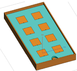
Figure 10 4 x 2 element patch array with ground plane.
Reusing the layouts from the three individual delay shifters, the antenna feed board was designed to mate to the backside of the antenna radiator board. The top and bottom element of each vertical column are fed with couplers, which provides unequal power for tapering and enhancing sidelobe suppression. Equal length lines were used to properly phase the inner and outer pairs. To reduce transmission line losses, microstrip lines transitioned to coplanar lines for the delay shifter layouts. Figure 9 shows the feed network with the three types of delay shifters, the combination of microstrip and coplanar waveguide and a USB control in the lower right.
The radiating elements were designed as planar patches backed with a ground plane, which provides a low profile (see Figure 10). The feed position and patch shape were chosen for linear polarization, with dual polarization angle coverage. Antenna efficiency is determined mainly by the losses in the substrate between the elements and the ground plane. To achieve good efficiency, a low loss PTFE with a height of 0.187 in. was selected, with a simulated efficiency of -0.3 dB. Since ground currents from the feed network transmission lines can distort the antenna radiation pattern, the antenna ground plane was separated from the feed board ground plane, which solved several other mechanical issues.
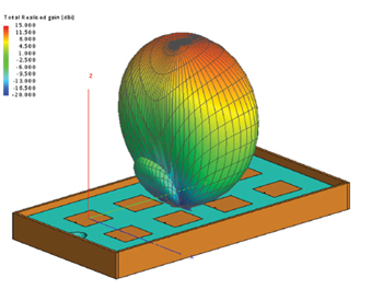
Figure 11 Array 3D gain pattern, azimuth at boresight and elevation +6.5°.
The element spacing in the array is an important design variable. Higher spacing usually results in higher peak lobe gain but increases the undesired grating lobe when the antenna is operating at high steering angles. The clean spurious lobe beam steering range is also determined by the number of rows and columns in the array. Since the design was selected to have only two columns, together with a large azimuth steering range, a traditional λ/2 spacing was selected.
To achieve lower sidelobes in the radiation pattern, -20 dB Taylor amplitude tapering was used in the elevation plane. With only four rows in the array, this tapering applies to the top and bottom rows, with no tapering possible across the two columns, i.e., the azimuth plane. To implement the tapering, rather than power dividers and attenuators, two couplers were used to feed the outer elements, which significantly improves the antenna system efficiency versus traditional methods. A simulated antenna pattern is shown in Figure 11, and the simulated system efficiency in all 12 beam states - three in azimuth and four in elevation - is shown in Figure 12. A simple USB interface controls the delay shifters steering the beam.
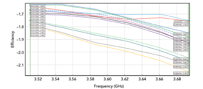
Figure 12 Simulated antenna efficiency vs. 12 switching states.
The antenna design was performed using Altair FEKO, a 3D electromagnetic (EM) tool which has method of moments, finite element, finite difference time domain and hybridization solver engines. The high-level design was performed using the finite array tool, which drastically reduced the simulation time and memory. The feed network was designed with Keysight Genesys using the S-parameter files for the delay shifters exported from the EMPro EM simulator. The completed feed network was then exported as a nine-port S-parameter file (one feed port and eight antenna ports) used in the antenna radiation pattern simulation in FEKO.
MEASURED PERFORMANCE
For antenna testing, a plastic 3D-printed radome was designed with transparent windows on the front and back, which shows the interconnection of the delay shifters (see Figure 13). Radiation tests confirm the beam can be controlled in both azimuth and elevation in three and four steps, respectively (see Figure 14). The overall efficiency of the antenna system was greater than 40 percent with greater than 10 dBi gain at a beam position of +6.7 degrees. As the beam was steered to greater angles, the loss in both the delay shifters and antenna elements increased slightly, reducing efficiency.
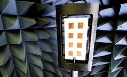
Figure 13 CBRS antenna in anechoic chamber.
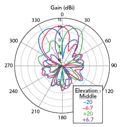
Figure 14 CBRS antenna measured radiation patterns.
SUMMARY
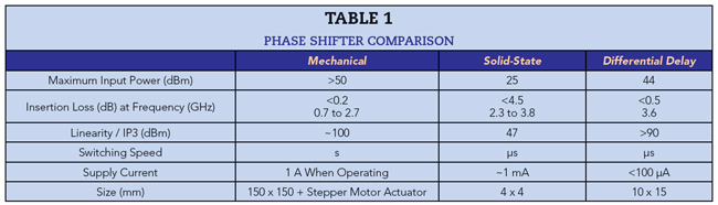
A novel DDS was designed, mimicking the traditional mechanical RET phase shifters yet using the discrete states of a high performance MEMS switch to emulate the positioning of an analog phase shifter. Implemented in a CBRS antenna yielded a highly efficient and lightweight antenna demonstrator, able to change the position of the beam within 10 μs - impossible with a mechanical phase shifter. Table 1 compares the performance of the DDS design to the mechanical and typical solid-state phase shifters. The main performance benefits of the DDS design are power handling, power consumption, IP3 and insertion loss. The broadband capability of the DDS enables it to be extended into the mmWave bands to support future beam steering antenna systems for 5G, aerospace and defense. Other planned design improvements include increasing the integration to realize simpler surface-mount designs and reduce the footprint.
Acknowledgment
This article reflects the contributions of Christopher Mobbs, consultant; Mats Lindstrom, CEO of RF2B; and Marten Seth, a senior systems applications engineer at Menlo Micro.