
In next-generation 4G/5G telecommunication systems, it is required that the radio transmitter and the power amplifier-the key part of the transmitter-operate with high efficiency over a wide frequency range, to provide multi-band and multi-standard concurrent operation. In these systems, with increased bandwidths and high data rates, the transmitting signal is characterized by high peak-to-average power ratio (PAPR) due to wide and rapid variations of the instantaneous transmitting power. It is very important to provide high efficiency at both maximum output power and lower power levels, typically ranging from 6 dB back-off and less, over a wide frequency bandwidth. Different 3GPP LTE-Advanced bands for 4G/5G systems, with up to 40 MHz channel bandwidths, are expected to be covered: tri-band (SMH, CLR, GSM) from 0.7 to 1 GHz, tri-band (DCS, PCS, IMT) from 1.8 to 2.2 GHz, dual-band (IMT and IMT-e) from 2.1 to 2.7 GHz or multi-band from 1.8 to 2.7 GHz. By using GaN HEMT technology and innovative Doherty architectures, average efficiencies of 50 to 60 percent for output powers up to 200 W can be achieved, significantly reducing transmitter cost, size and power consumption.
For a conventional Doherty amplifier with a quarter-wave impedance transformer and a quarter-wave output combiner, the measured power-added efficiency of 31 percent at about 43 dBm-6 to 7 dB back-off from the saturated output power-has been achieved across the frequency range from 1.5 to 2.14 GHz.1 To improve the broadband performance of the conventional Doherty amplifier, the output network can be composed of two quarter-wave impedance inverters with reduced impedance transformation ratios.2 For broadband combining, an output quarter-wave transmission line with fixed characteristic impedance can be replaced by a multi-section transmission line with different characteristic impedances and electrical lengths, which enables frequency coverage from 2.2 to 2.96 GHz.3 In this case, broadband matching is realized by applying the simplified real frequency technique with the desired frequency-dependent optimum impedances. However, nonlinear optimization of the entire Doherty amplifier system makes the design complicated to simulate and results in a large size for the final board implementation.
A high peak power of 350 W has been achieved across the lower frequency band of 760 to 960 MHz using a modified combining scheme with two quarter-wave lines in the peaking path.4 Using an asymmetric Doherty architecture, saturated power greater than 270 W, linear gain greater than 13 dB and a drain efficiency greater than 45 percent at 8 dB back-off has been achieved across 2.5 to 2.7 GHz.5
ACHIEVING BROADBAND PERFORMANCE
A multi-band Doherty amplifier can be achieved when all of its components are designed to provide their corresponding characteristics over the required bandwidth of operation. The carrier and peaking amplifiers should provide broadband, high efficiency performance when, for example, their input matching circuits are designed as broadband. The load network generally comprises a lowpass, lumped or transmission line structure with two or three matching sections. Therefore, it is very important for matching circuits to be partly implemented inside the device package to achieve an average output power of 40 W and higher, especially for the input matching circuit, given the very low device impedance across the required frequency range.
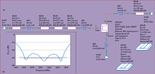
Figure 1 Fig. 1 Equivalent circuit of the packaged device (a) and |S11| performance (b).
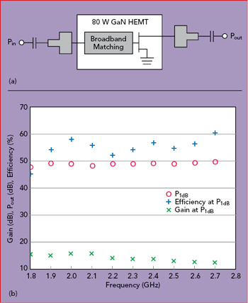
Figure 2 Class AB PA with broadband conjugate matching (a) and measured performance (b).
Figure 1 shows the equivalent circuit of a device with input matching elements inside the package and the small-signal |S11| at the input of the internal input matching circuit, including the package lead frame. The 50 V device, fabricated by Sumitomo Electric Device Innovations, has six basic 15 W GaN HEMT cells connected in parallel and capable of providing a combined saturated output power of more than 80 W across the entire band from 1.8 to 2.7 GHz. The three-section microstrip transformer is implemented using an alumina substrate with a high permittivity of 250 and a thickness of 0.16 mm, yielding a compact structure transforming the device input impedance to 10 Ω, with an |S11| less than −25 dB.
Generally, the multi-band impedance transformer required for broadband operation is represented as a configuration of N cascaded transmission lines (N ≥ 2) with different characteristic impedances.6 For example, to match the output impedance of 25 Ω to a load impedance of 50 Ω, the broadband output transformer can be realized using a two-section microstrip line, where the characteristic impedance of the first quarter-wave section is 30 Ω, and the characteristic impedance of the second quarter-wave section is 42 Ω. In this case, the input impedance magnitude variation of ±0.5 Ω and phase variation of ±1 degree can be achieved from 2 to 2.8 GHz, simultaneously covering the 2.1 GHz (2.11 to 2.17 GHz) and 2.6 GHz (2.62 to 2.69 GHz) WCDMA/LTE bands.7 At the same time, magnitude variations of ±1 Ω and phase variations of ±2 degrees can be achieved over a 1 GHz bandwidth from 1.9 to 2.9 GHz, which means that reducing the mid-band frequency to 2.3 GHz can result in simultaneous tri-band operation, i.e., including an additional 1.8 GHz DCS/WCDMA/LTE band (1805 to 1880 MHz).
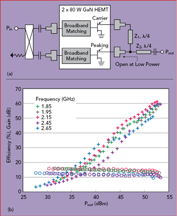
Figure 3 Doherty PA using dual-path packaged transistor (a) and measured performance (b).
Figure 2a shows the simplified schematic of a single-ended, 80 W GaN HEMT power amplifier operating in class AB mode, with external input and output matching circuits, which operates from 1.7 to 2.7 GHz. The input and output matching circuits, implemented on an RO4350 substrate, represent a two-stepped microstrip line transformer, with each line section a different characteristic impedance and electrical length. The matching network provides a conjugate-match with the device input and equivalent output impedance at the fundamental frequency. With this design, an output power at 1 dB gain compression (P1dB) of greater than 48 dBm, a power gain greater than 12 dB and drain efficiency greater than 52 percent were measured across 1.8 to 2.7 GHz, as shown in Figure 2b. Previously, drain efficiencies greater than 60 percent were reported between 1.9 and 2.9 GHz with commercial 45 W GaN HEMT transistors, using the simplified real frequency technique to determine optimum impedances and element values for the highest efficiencies across the frequency range.8
The classic two-stage Doherty amplifier has limited bandwidth in the low-power region, since it is necessary to provide an impedance transformation from 25 to 100 Ω when the peaking amplifier is turned off. This results in a loaded quality factor QL = √100/25 − 1 = 1.73 at 3 dB output power reduction, which is sufficiently high for broadband operation. At high-power levels, achieving broadband output matching of the carrier and peaking amplifiers with a broadband output quarter-wave transformer, it is possible to maximize the frequency bandwidth.
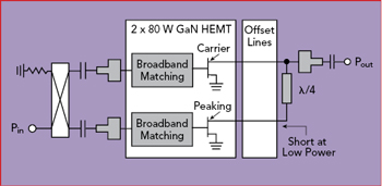
Figure 4 Broadband inverted Doherty PA.
Figure 3a shows the circuit diagram of a conventional two-stage Doherty amplifier implemented on 20 mil RO4350 substrate and using two, 80 W GaN HEMT power transistors with internal input matching and metal-ceramic flange packages. The input and output matching circuits are microstrip lines of different electrical lengths and characteristic impedances for the two-stepped structures. The input splitter is a broadband coupled-line coupler from Anaren (model X3C17A1-03WS), which provides a maximum phase balance of ±5 degrees and an amplitude balance of ±0.5 dB from 690 to 2700 MHz. Figure 3b shows the measured power gain and drain efficiency at five in-band frequencies. A power gain of more than 9 dB is achieved from 1.8 to 2.7 GHz, with drain efficiencies of about 60 percent at an output power corresponding to 3 dB gain compression (except at the high end of the band) and between 40 and 50 percent at 6 dB back-off. Given the bandwidth limitations of the conventional structure, the Doherty effect is not strong across the full band, with lower efficiency at the higher frequencies.