
Redundant Transmission and Antennas
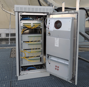
Figure 3 Rack Shelter with devices for electro-optical conversion. (Source: DEV Systemtechnik)
In order to ensure continuous signal availability, even in the case of failure of a part of the transmission chain, routes are designed redundantly. If a section of the route fails, a backup can take over the signal transmission of the failed part. Implementing one redundancy unit for each transmission part (a so-called 1+1 redundancy) would lead to an increase of costs. Since backup equipment is only required in the rare case of a primary path failure, a more effective solution is to implement an N+1 redundancy. With N+1 redundancy, “N” number of primary units can share the same (1) redundancy unit, thanks to intelligent switching devices on both sides of the transmission line.
The concept of hedging against dropouts with redundancy is not only applied to transmission lines. Antenna fields can also be protected against failure. A motorized steerable backup antenna can be employed to restore failure of 1 to N number of fixed (non-steerable) antennas in a facility. The backup antenna, controlled from an Antenna Control Unit (ACU), can be pointed to different satellite positions in order to restore one of several fixed position antennas. This antenna failure backup restoral can be accomplished using a Redundancy Switch typically installed in an antenna rack shelter. It is also possible to install the switch behind the optical fiber transmission link.
If the redundancy switch detects a malfunction of the signal from one of the fixed antennas, the ACU points the motorized steerable backup (redundancy) antenna to the faulty antenna’s satellite position. Once peaked on the correct satellite, the backup antenna can receive and restore the signal in place of the faulty antenna. The signal outage is thus minimized.
For operators that do not have a management system that can perform the switching automatically, or do not wish to perform the integration, there is a special solution from DEV Systemtechnik: the DEV 1993 Antenna Redundancy Switch monitors and switches the signals of connected antennas, and it can completely take over the control of the ACU in the case of a dish failure. As a result, it creates a closed, automated system for achieving antenna redundancy without the need for an external management system.
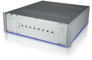
Figure 4 Antenna Redundancy Switch DEV 1993. (Source: DEV Systemtechnik)
Site Diversity
Failures are not only caused by technical defects. Severe weather events can affect entire antenna farms, due to attenuation of satellite signals caused by rain and atmospheric moisture, which more severely attenuates higher satellite frequencies (Ku-, Ka-Band). However, since outage-causing weather effects tend to be geographically localized, a concept called Site Diversity can be implemented to maximize uptime and minimize weather effects. With this Site Diversity approach, a redundant downlink antenna facility is built in another location, typically at least 50 to 150 km away. RF-over-Fiber (RFoF) is used to link the two sites.
The redundant facility would typically be smaller, possibly unmanned, and may only include the primary satellite dishes, outdoor equipment and shelter. At the “Diversity Site”, the downlinked electrical signals are converted for fiber transmission, multiplexed and sent to the main headend receive equipment via fiber optic links.
Since the purchase of fiber optic telecommunications service may be required for the fiber connection, and this can incur a costly recurring fee, methods such as CWDM (Coarse Wavelength Division Multiplexing) and DWDM (Dense Wavelength Division Multiplexing) are typically used to bandwidth-efficiently combine and transport the signals from the antenna Diversity Site to the main site. With CWDM or DWDM, using different wavelengths, up to 16 or 80 different signals can be transmitted over a single optical fiber. At the RF-over-Fiber receive location a demultiplexer divides the multiplex back to individual channels and paths. The switching between the antenna sources can also be managed by a 1+1 redundancy switch.