
When most people hear the term microwave, they think of microwave ovens. That is natural and perfectly appropriate, since microwave ovens operate at 2.45 GHz, which is in the microwave and wireless frequency band. The microwave oven is a device with a high-power electron tube (magnetron) that generates and radiates electromagnetic energy into food to be prepared. It cooks the food by heating the moisture inside the food, i.e. it cooks from the inside to the outside.
Figure 1 is a diagram of the electromagnetic spectrum illustrating the respective frequency bands for common communications, navigation and radar applications. Some of the more familiar applications are AM and FM broadcast bands for radio, television channels, cellular phones, global positioning systems (GPS), personal communications services (PCS) and direct broadcast satellites (DBS). Each of these applications has a different frequency of operation. They are in an FDMA mode, i.e. operating over a specified band of frequencies all the time. There is no planned time gap and no time sharing of stations or channels.

Figure 1 Electromagnetic spectrum.
Some applications, in particular, are summarized below:
Radar
Overview
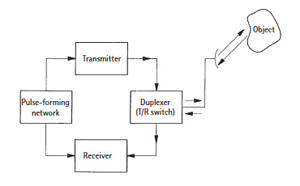
Figure 2 Basic radar system.
A classical radar (see Figure 2) sends out a high-power short duration microwave pulse generated by a transmitter through a beam-focusing antenna. The pulse is controlled by a pulse-forming network and begins a time sequence when it is transmitted. The pulse strikes an object or target that reflects the energy back through the antenna to the radar receiver. The time it takes for the pulse to be transmitted, bounce off an object and be received determines the distance that object is away from the radar antenna. The angle of the antenna beam to the object determines the azimuth and/or elevation.
An important block in Figure 2 is the duplexer, or transmit/receive (Tx/Rx) switch. The duplexer is a circuit that switches the radar’s antenna from the transmitter to the receiver at the proper time so that the transmitted signal does not damage the receiver. It also allows the very low level signal coming back from an object to be routed to the receiver. The duplexer can be a physical switch or a series of transmission lines that perform the switching function.
To further understand radar concepts, it is necessary to define some additional terminology:
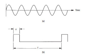
Figure 3 Waveforms; continuous wave (a), pulse (b).
- Continuous wave (CW) (see Figure 3a) refers to a signal that is continuously on; i.e. there is no time that the signal is interrupted or is off.
- Pulse transmission (see Figure 3b), is the heart of a radar system and what actually enables the operation. A pulse signal supplies power for only a very short amount of the time (5 to 10 percent or less). This enables high peak powers, usually not possible with CW systems, because of the high average power required to be continuously on. If the power is on all the time, there is also a problem with system components being able to dissipate wasted energy in the form of heat.
- Pulse width (τ) is how long the signal is on (measured in units of time (e.g. seconds, milliseconds, microseconds).
- Pulse repetition rate (PRR), alternatively referred to as pulse repetition frequency (PRF) is the number of times the pulse is repeated each second. Its inverse is the PRT, or pulse repetition time designated as represented by “T” in Figure 3b.
- Duty cycle is the ratio of the pulse width, τ, to the pulse repetition time, T or τ/T. The duty cycle is 5, 6, 7, 10 percent or whatever percentage of time that the signal is present. Looking at it another way, it is the time that the signal is actually doing something, or is on duty, compared to the total amount of time available.
- Peak power is the amount of power present at the top of the pulse. In Figure 3b, the peak power is the amplitude of the pulse over the duration, τ. Peak power is usually high, but it is present for only a short period of time. Many components are characterized with both a peak and CW power specifications for use in either application.
- Average power is defined as the peak power multiplied by the duty cycle. Power is available for the period of time that a pulse is on (peak power). Subsequent pulses contribute to the system average power based on the pulse repetition rate and the pulse width (i.e. the duty cycle).
The applications and functions of radar systems can be categorized as search and warning, tracking and measurement and imaging.