

AAS is the general term used to describe an antenna system using novel techniques to improve the performance and spectral efficiency of 5G transceivers. These techniques include adaptive beamforming, multiple input multiple output (MIMO), and space division multiple access (SDMA). The AAS requirements to meet 5G applications are specified in terms of frequency bands, antenna element properties, array configurations and beamforming characteristics. AAS technical requirements from the latest standards are summarized and some strategic approaches for satisfying those requirements are provided.
The rapid and continuing expansion of wireless applications has encouraged the mobile broadband industry, transforming both businesses and lives. While 4G long-term evolution (LTE) has room to continue expanding in both advanced and emerging markets, with 5G development accelerating, engineers are planning another ten-fold or greater increase in throughput. To the human-based wireless demand, tens of billions of communicating machines, the Internet of Things, will be added. As interest grows in faster wireless services, wider operating bandwidths are needed for larger data transmission capacities.
One of the most important components of these wireless systems is the AAS. An AAS must combine multiband and wideband performance, high radiation efficiency and beamforming capabilities. There is intensive research and development in the field of AAS design for 5G applications.1 The AAS market is growing at a high cumulative annual growth ratio (CAGR) leading to an increasing interest by industry to expand development.2
The International Telecommunications Union (ITU) plays an important role in determining requirements to advance the mobile wireless industry known as the International Mobile Telecommunication (IMT) system.3 The 3rd Generation Partnership Project (3GPP) is a consortium comprising several standards organizations that develop mobile communication protocols.4
The spectrum currently allocated to IMT can be classified into two major categories: spectrum below 6 GHz (sub 6 GHz) and spectrum above 24 GHz or mmWave. The ITU World Radio communication Conference (WRC) updates the frequency allocation table every four years. The results of ITU WRC-19 indicate that future mobile devices should support different frequency bands in the sub 6 GHz spectrum starting from 450 MHz as well as mmWave starting from 24.25 GHz.5
Besides being able to operate over these frequency bands, an AAS must meet other technical requirements in terms of its array configuration and beamforming capabilities to satisfy the needs of 5G systems. This tutorial summarizes AAS requirements and proposes some strategic design guidelines.
5G AAS Frequency Requirements
One of the key drivers for 5G development is data rate – 20 Gbps and 10 Gbps peak rates for downlink and uplink respectively. Use of the mmWave spectrum for communication is a promising and concrete approach to enable wider channel bandwidths from 100 MHz to 1 GHz.
An AAS uses beamforming and MIMO techniques for improving the performance of 5G systems and must support the allocated frequency bands, enable multi-user beamforming allowing multiple user beams to share time- and frequency-domain resources and be highly integrated.6
The frequency bands identified for IMT in the ITU Radio Regulations (RR) edition 2020 and allocated to mobile by the 3GPP are arranged into two categories, FR1 and FR2 (see Table I). FR1 includes sub 6 GHz frequencies while FR2 denotes mmWave frequencies.
Table II shows the frequency bands allocated to mobile service including the band names and corresponding 3GPP band numbers. Note that different regulatory provisions are applied to each band.
Global, regional or country identifications for each band are contained in the Table of Allocations and in the referenced footnotes of Article 5 of the ITU RR.7 The ITU frequency allocations are categorized for different radio regions addressing specific countries while the 3GPP allocation includes all harmonized frequency allocations. From an industrial point of view, 5G antennas should address the 3GPP frequency bands.8 The employed frequency bands for 5G, however, might be different, region-by-region based on the ITU RR.
TABLE I
3 GPP Frequency Ranges8
Frequency Range Designation |
Corresponding Frequency Range (MHz) |
FR1 |
410 to 7,125 |
FR2 |
24,250 to 52,600 |
TABLE II
3GPP Frequency Bands8
Spectrum (MHz) |
Band Name |
3GPP Bands |
410 to 427 |
410 |
n87, n88 |
450 to 470 |
450 |
n31, n72, n73 |
470 to 694 |
600 |
n71 |
694 to 790 |
700 |
n12, n13, n14,n17, n28, n29, n44, n67, n68, n85 |
790 to 862 |
800 |
n20 |
814 to 894 |
850 |
n5, n18, n19, n26 |
880 to 960 |
900 |
n8 |
1,427 to 1,518 |
1,500 |
n21, n32, n45, n50, n51, n74, n75, n76, |
1,695 to 2,200 |
1,700 |
n4, n66, n70 |
1,710 to 1,880 |
1,800 |
n3 |
1,850 to 1,990 |
1,900 |
n2, n25, n35, n36, n37, n39 |
1,920 to 2,200 |
2,100 |
n1, n65 |
2,300 to 2,400 |
2,300 |
n30, n40 |
2,500 to 2,690 |
2,600 |
n7, n38, n41, n69, n90 |
3,300 to 3,400 |
3,300 |
n52, n77, n78 |
3,400 to 3,700 |
3,500 |
n42, n48, n49, n77, n78 |
3,600 to 3,800 |
3,700 |
n43, n77, n78 |
4,400 to 5,000 |
4,800 |
n79 |
24,250 to 27,500 |
26,000 |
n258 |
26,500 to 29,500 |
28,000 |
n257, n261 |
37,000 to 40,000 |
39,000 |
n260 |
39,500 to 43,500 |
42,000 |
n259 |
Generally, the mobile frequency bands listed in Table II can be divided into three classifications as follows:8
- Low Band (f < 1 GHz)
- Mid Band (1 GHz < f < 6 GHz)
- High Band (f > 24 GHz)
While the low band frequencies provide wide area and deep indoor coverage with limited capacity, high band frequencies offer larger bandwidth and higher capacity, but with limited coverage. The mid band is a middle ground between coverage and capacity. 5G operators use certain frequency bands from all three classifications, called carrier aggregation (CA), to leverage the best characteristics for a given application.
Some CA configurations specified by 3GPP among FR1 bands are listed in Table III. The standard example of CA between FR1 and FR2 is also shown in Table IV. For example, the configuration n3+n28+n77+n257 uses all three mentioned classifications. Currently, the frequency band 3.4 to 3.6 GHz (n42, n77, n78) in mid band and 28 GHz (n257) and 39 GHz (n260) in the high bands are being used extensively for 5G early deployments.
TABLE III
Some inter-band CA configurations8
CA |
Bands |
Two Bands |
n1+n3 n1+n7 n1+n28 n1+n40 n1+n77 n3+n41 n3+n77 n5+n77 n20+n28 n25+n77 |
Three Bands |
n1+n3+n7 n1+n3+n28 n1+n3+n78 n1+n8+n78 n66+n71+n78 |
Four Bands |
n1+n3+n7+n28 n1+n3+n7+n78 n1+n3+n28+n78 n25+n41+n66+n71 |
TABLE IV
Some CA between FR1 and FR28
CA |
Bands |
Two Bands |
n1+n257 n1+n258 n2+n260 n2+n261 n3+n257 n5+n260 n5+n261 n25+n258 n28+n257 n40+n258 n41+n260, n48+n261 |
Three Bands |
n1+n40+n258 n1+n77+n257 n3+n28+n257 n3+n77+n257 n40+n78+n258 |
Four Bands |
n1+n77+n79+n257 n1+n78+n79+n257 n3+n28+n77+n257 n3+n28+n78+n257 |
Alongside the standard 3GPP bands, the mmWave frequency bands with global IMT identification in RR 2020 are listed in Table V. Some are allocated to mobile by 3GPP and the others will be in the allocation process soon. Moreover, some frequency bands are under study for possible IMT identification by the decision of WRC-23 (see Table VI).
TABLE V
mmWave Frequency bands with global IMT identifications7
Spectrum (GHz) |
Bandwidth (GHz) |
24.25 to 27.5 |
3.25 |
37 to 43.5 |
6.5 |
45.5 to 47 |
1.5 |
47.2 to 48.2 |
1 |
66 to 71 |
5 |
TABLE VI
Frequency Bands Under Study for IMT Identification7
Spectrum (MHz) |
Bandwidth (MHz) |
6,425 to 7,025 |
600 |
7,025 to 7,125 |
100 |
10,000 to 10,150 |
150 |
Tables III through VI imply that 5G antenna systems should support the standard frequency band configurations in 5G networks. With respect to AAS, considering the industry approach for using AAS in different frequency bands, the recommendation in Table VII is extracted.
While the implementation of AAS in sub-1 GHz bands is difficult due to size constraints, AAS is an advantage for mid bands and is essential for the high bands to overcome propagation loss and increase system performance. Any proposed 5G antenna design should be in alignment with the defined frequency bands and recommendations in terms of AAS necessity.
Table VII
AAS Recommendations
Band Type |
AAS Necessity |
Low Band |
Non-AAS |
Mid Band |
Non-AAS & AAS |
High Band |
AAS |
AAS Properties
AAS is the general term used to describe antenna systems using techniques for improved performance and spectral efficiency of 5G transceivers. These techniques include adaptive beamforming, MIMO and SDMA.6 The major advantage of an antenna array over a single antenna element is its electronic scanning capability, where the main lobe can be steered in any direction by changing the phase of the excitation current at each array element. Furthermore, by also controlling the magnitude of the excitation current, a large variety of radiation patterns and sidelobe level characteristics can be produced.
An adaptive antenna (also called “smart antenna” in mobile communication applications) can go a step further than a phased array by directing its main lobe (with increased gain) in a desired direction and creating radiation pattern nulls in the directions of interference or jammers.
MIMO and spatial multiplexing can transmit multiple data streams by beamforming each data stream using the same time and frequency resource. The purpose of MIMO is basically to increase throughput by receiving multiple streams of data with reduced power per stream when the received signal quality is high compared to receiving one stream with full power.1, 6
Overall array performance depends on the following factors:
Geometry
AAS geometry is based on the geometry of a single element and its arrangement in an array. A simple rectangular patch antenna as the basic antenna element and can be used in an array for one frequency band; however, the geometry should be modified for multiband performance and dual polarization.
From a practical standpoint, in many arrays all antenna elements are designed to be identical. This considerably simplifies the analysis. The array radiation pattern consists of the element pattern, and array factor (AF). The total pattern in the far-field is then the product of the element pattern and the AF.6-9
The most common array configurations are linear and planar. Figure 1 shows the geometry of a rectangular M × N planar array with an inter-element spacing d. Multi-antenna techniques are generally applicable to any frequency band or radio application and can be implemented using passive or active antennas.9-11
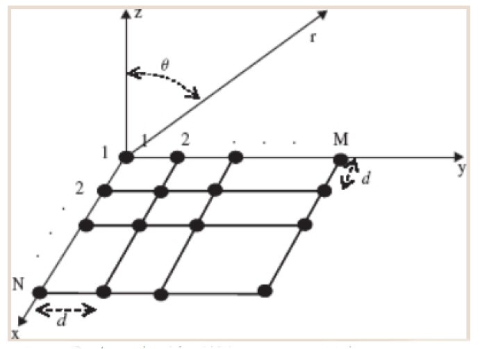 Fig.1 Rectangular M × N planar array with inter-element spacing d.
Element Spacing
In an AAS, the antenna elements are placed close to each other to efficiently use the area. This creates mutual coupling from surrounding elements. Mutual coupling affects antenna array efficiency and radiation pattern characteristics; therefore, the separation between adjacent elements as a function of the wavelength is an important parameter.
Excitation
Adjusting the phase and amplitude of the excitation of each individual element directs radiated energy in several different paths (direction and/or polarization). Steerability is achieved by individually controlling the amplitude and phase of smaller parts of the antenna array.
Beamforming
Beamforming is the concentration of radiated power toward a specific direction in space and nulling it in undesired directions. Beamforming can be implemented in the analog domain, digital domain and in a hybrid configuration.
Analog beamforming uses various components such as waveguide filters and phase shifters to form a pre-defined beam. This structure requires a single RF chain and provides a single data stream for transmission or reception.9-11
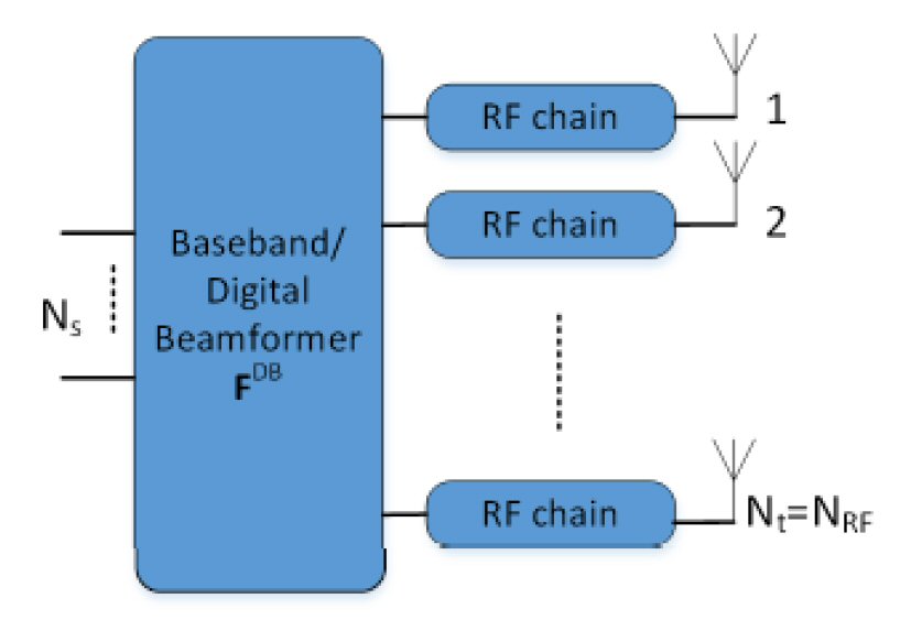
In digital beamforming, time delay and amplitude weights are applied to each element. Thus, each element of the antenna array has a separate RF chain, and transmit/receive a different baseband signal, enabling multiple data streams via the processor (see Figure 2). These beams can be fixed in orientation or adaptively formed, depending on the mechanisms employed.9-11

Fig. 2 Digital beamforming architecture.
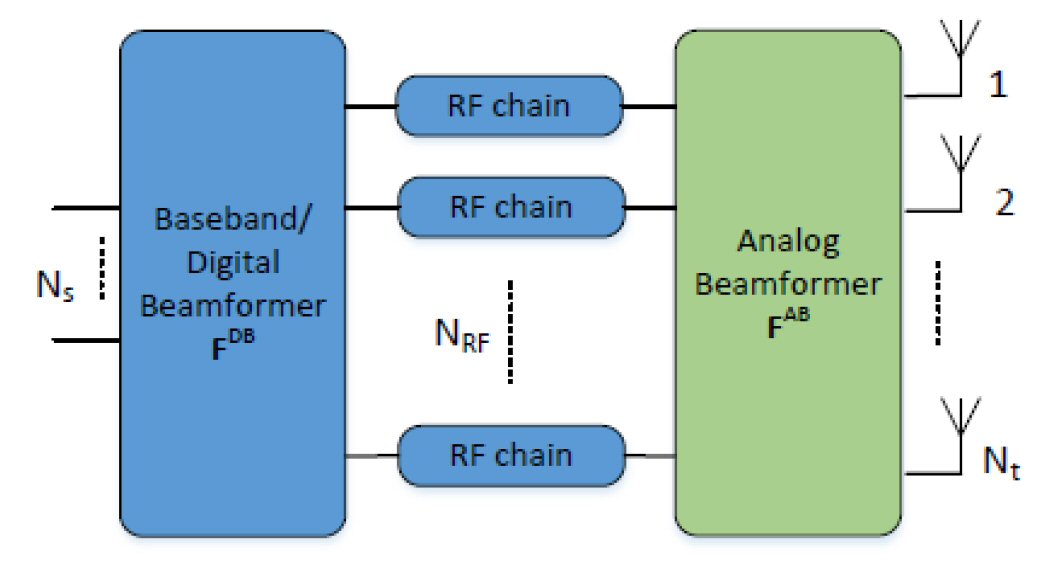
Hybrid beamforming combines analog and digital beamforming to exploit the advantages of both configurations. In hybrid beamforming, each data stream is a digitally beamformed signal transmitted by a separate RF chain associated with multiple antenna array elements.9-11
The three beamforming configurations are shown in Figure 3. The analog architecture is simple while providing restricted pre-defined beams. Digital beamforming offers more flexible beamforming performance but with more complexity. The hybrid architecture provides a compromise between complexity and beamforming performance.12
 (a)
(a)
 (b)
(b)
 (c)
(c)
AAS Configurations
The AAS consists of a feed network, a phase shifter and a radiator stack (see Figure 4). All parts can be designed independently and integrated in a unit package. The independent designs should be accomplished after investigating the main characteristics of 5G new radio (NR) and its requirements.13-15
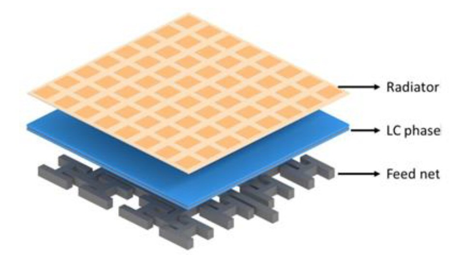
Fig. 4 Conceptual illustration of the AAS structure.
Radiator Stack
Antennas for mobile applications are commonly developed as passive rectangular planar structures. Planar antennas for wireless devices are mainly constructed using printed circuit technology. In modern wireless communication applications, the chosen antenna elements are often small microstrip patches. The purpose of using a patch antenna array is to enable high-gain beams and make it possible to steer those beams over a range of angles.16, 17
There are two main considerations, antenna miniaturization and multiband behavior. In antenna design, multiband behavior can be achieved by modifications to the main radiator using several radiators for different resonances or extending a radiators’ length to achieve multiple resonant modes. Because creating several radiating elements occupies more space, miniaturization techniques should increase electrical length while the physical space remains constant.16, 17
An AAS typically comprises rows and columns of individual dual-polarized antenna elements that can be divided into subarrays with each subarray connected to two radio chains, normally one per polarization. Figure 5 shows a typical 8 × 8 element antenna using dipole radiators with ± 45 degree polarization, having 128 radio chains. The main requirements of this AAS, according to the standard recommendations, are listed in Table VIII.1
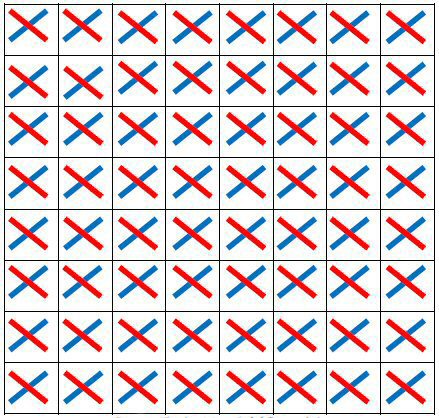
Fig. 5 Typical 8 × 8 AAS model.
The main radiator of an antenna plays a major role in determining its resonant frequency. The main radiator element can be modified by changing its configuration in such a way that it occupies a limited area/volume with multiband behavior using different approaches such as a special geometry, dielectric resonators and fine-tuned defined configurations of slots.18
An alternative solution for miniaturization is better use of the ground plane.18 Although main radiator geometry plays a major role in antenna performance, the importance of the ground plane for radiating current should not be neglected. Ground plane considerations include size, location of radiating element within the ground plane area and the insertion of slots.17-19
TABLE VIII
AAS Main Operating Requirements
Operating Frequency Range |
One / Multi-Frequency Bands from Table II |
Array Size |
8 × 8 |
Polarization |
Dual Polarized |
Element spacing |
0.5λ |
Horizontal/vertical beamwidth of single element (degree) |
65º for both H/V |
Sidelobe Suppression |
> 10 dB |
Operational range of scan angles in the horizontal plane |
±60 degrees |
Operational range of scan angles in the vertical plane |
±15 degrees |
Beamformer and Feed Network
Beamforming can be implemented in analog, digital and hybrid configurations.20 Analog beamforming is normally configured in RF using waveguide filters and phase shifters to create a pre-defined beam. It is easy to implement but has a limited number of fixed beams. Digital beamforming employs a separate RF chain for each array element, leading to a more complicated structure and higher power consumption, but is flexible and efficient. Hybrid beamforming uses both analog and digital beamforming as each RF chain is associated with multiple antenna elements.20, 21
Analog beamformers are important components of hybrid beamforming systems. Several different analog RF beamforming networks have been proposed. Most employ Butler matrix and Rotman lens topologies. The Butler matrix is an analog implementation of the fast Fourier transform, including couplers and phase shifters. It exhibits significantly narrower bandwidths than most wideband antenna arrays, however. A Rotman lens is passive, implementing true time delay with relatively wideband performance.22-25 The main advantage of the Rotman lens as compared to the Butler matrix is lower weight and hardware cost while exhibiting wider bandwidth.20
AAS Array Partitioning
The AAS array can be partitioned into subarrays, where a subarray is defined as a subset of dual-polarized elements pairs connected to two feeds, one for each polarization. It is assumed that each element pair of a planar array with Kv rows and Kh columns of dual-polarized element pairs is partitioned into non-overlapping rectangular subsets of element pairs, referred to as subarrays with Mv rows and Mh columns known as an array of subarrays.1
The performance of multi-antenna solutions in mobile communication depends on the deployment scenario. The deployment scenario is categorized as dense urban, urban, rural, and fixed wireless access (FWA). Multi-antenna performance is also affected by algorithm choice and antenna configurations. Figure 6 is an illustration of a typical antenna configurations for an 8 × 8 AAS.
Antenna configurations are indicated by (Mv × Mh)SA ( Nv × Nh), where Mv and Mh are the number of vertically and horizontally dual-polarized antenna element pairs in the subarray respectively, and Nv and Nh are the number of vertically and horizontally stacked subarrays, respectively. The number of RF chains with dual-polarized antennas are represented as 16T, 32T, 64T and 128T.1
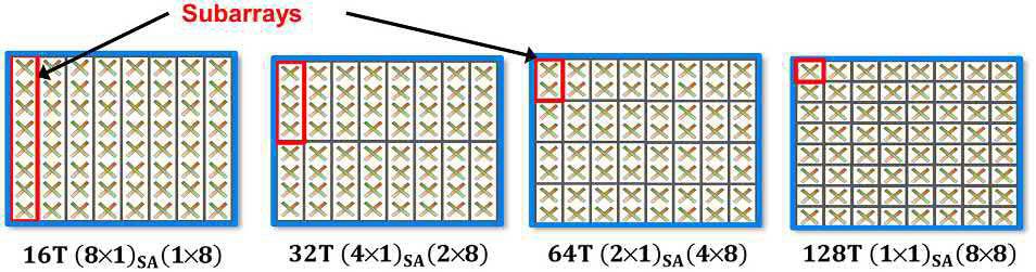
Fig. 6 An 8 × 8 subarray configuration with the number of RF chains ranging from 16 to 128.1
Analysis1 shows that, for dense urban and urban area, reducing the subarray size, as it enables more efficient vertical domain beamforming, will increase capacity. For example, for an 8 × 8 AAS, a 64T AAS based on 2 × 1 subarrays provides almost four times more capacity than a 16T AAS based on 8 × 1 subarrays.
In contrast, a rural scenario requires an antenna with a large area and horizontal domain beamforming. Vertical domain beamforming does not provide any significant gains. Therefore, large vertical subarrays are appropriate for rural areas as this maximizes gain while reducing the number of RF chains.
For a dense area, a small subarray size is recommended, while for rural and fixed access, larger subarrays are appropriate. A deployment recommendation for an 8 × 8 AAS advises implementing a 64T – 2 × 1 subarray for a dense urban high-rise, a 32T – 4 × 1 subarray for an urban low-rise and a 16T – 8 × 1 subarray for rural and fixed access (see Table IX).1 Larger subarrays lead to more complicated beamforming networks while small subarrays require more RF chains.
TABLE IX
AAS subarray configurations
Scenario |
Dense Urban |
Urban |
Rural& FWA |
Recommendation for an 8×8 array |
64T 2×1 subarray |
32T 4×1 subarray |
16T 8×1 subarray |
Conclusions
AAS is a powerful tool for 5G systems utilizing beamforming and MIMO techniques to significantly improve network capacity and coverage. Most of the 5G antenna research in recent years has focused on AAS components such as the antenna element, phased array antenna and beamforming, while the system realization is rarely found in the literature to date. As a result, research on 5G antennas may be not practically applied to real networks because they do not consider specific 5G requirements such as approved frequency bands and the unique antenna characteristics needed for different deployment scenarios.
The development of AAS as a growing industry and market demand based on the recently defined requirements by world standard institutions is progressing with the technology. This tutorial summarizes AAS requirements to help shape ongoing research on 5G antenna systems.
Acknowledgments
This work was supported by grant No. RD-51-9911-0024 from the R&D Center of Mobile Telecommunication Company of Iran (MCI) for advancing information and communications technologies.
References
- H. Asplund, D. Astely, P. Butovitsch, T. Chapman, M. Frenne, F. Ghasemzadeh, M. Hagström, B. Hogan, G. Jongren, J. Karlsson, F. Kronestedt and E. Larsson, Advanced Antenna Systems for 5G Network Deployments -Bridging the Gap Between Theory and Practice, Academic Press, 2020.
- “Advanced Antenna System Market Forecast and CAGR,” Fact.MR, September 2022. Web.
- “Modelling and Simulation of IMT Networks and Systems for Use in Sharing and Compatibility Studies,” ITU-R Recommendation M. 2101-0, February 2017.
- 3GPP. Web.
- “Final Acts WRC-19,” ITU, 2019. Web.
- “5G Antenna White Paper – New 5G, New Antenna,” HUAWEI, 2019. Web.
- “Frequency Arrangements for Implementation of the Terrestrial Component of International Mobile Telecommunications (IMT) in the Bands Identified for IMT in the Radio Regulations,” ITU-R Recommendation M. 1036-6, October 2019.
- “Release 16,” 3GPP. Web.
- W. L. Stutzman and G. A. Thiele, Antenna Theory and Design, 3rd Edition, Chapter 8 Array Antennas, John Wiley & Sons Inc., Hoboken, NJ, 2013.
- C. A. Balanis, Modern Antenna Handbook, Chapter 11 Arrays and Smart Antennas, John Wiley & Sons Inc., Hoboken, NJ, 2008.
- R. Monzingo, R. L. Haupt and T. Miller, Introduction to Adaptive Arrays, 2nd Edition, SciTech Publishing, Raleigh, NC, 2011.
- I. Ahmed, H. Khammari, A. Shahid, A. Musa, K. S. Kim, E. D. Poorter and I. Moerman, “A Survey on Hybrid Beamforming Techniques in5G: Architecture and System Model Perspectives,” IEEE Communications Surveys & Tutorials, Vol. 20, No. 4, 4th Quarter 2018, pp. 3060-3097.
- A. Osseiran, J. F. Monserrat and P. Marsch, 5G Mobile and Wireless Communications Technology, Cambridge University Press, Cambridge, UK, 2016.
- J. Rodriguez, Fundamentals of 5G Mobile Networks, John Wiley & Sons Ltd, Chichester, UK, 2015.
- W. Xiang, K. Zheng and X. Shen, 5G Mobile Communications, Springer International Publishing, Switzerland 2017.
- C. A. Balanis, Antenna Theory Analysis and Design, 4th Edition, John Wiley & Sons Inc., Hoboken, New Jersey, 2016.
- T. A. Milligan, Modern Antenna Design, 2nd Edition, John Wiley & Sons Inc., Hoboken, New Jersey, 2005.
- A. Kishk, Advancement in Microstrip Antennas with Recent Application, IntechOpen, 2013.
- R. J. Mailloux, Phased Array Antenna Handbook, Artech House Inc., Norwood, MA, 2005.
- J. Dong and A. I. Zaghloul, “Implementation of Microwave Lens for 360-Degree Scanning,” IEEE International Symposium on Antennas and Propagation, June 2009.
- J. Zhang, X. Yu and K. B. Letaief, “Hybrid Beamforming for 5G and Beyond Millimeter-Wave Systems: A Holistic View,” IEEE Open Journal of the Communications Society, Vol. 1, December 2019, pp. 77-91.
- C. Qin, F. -C. Chen and K. -R. Xiang, “A 5 × 8 Butler Matrix Based on Substrate Integrated Waveguide Technology for Millimeter-Wave Multibeam Application,” IEEE Antennas and Wireless Propagation Letters, Vol. 20, No. 7, July 2021, pp. 1292-1296.
- D. I. Lialios, N. Ntetsikas, K. D. Paschaloudis C. L. Zekios, S. V. Georgakopoulos and G. A. Kyriacou, “Design of True Time Delay Millimeter Wave Beamformers for 5G Multibeam Phased Arrays,” Electronics, Vol. 9, No. 8, August 2020.
- R. C. Hansen, “Design Trades for Rotman Lenses,” IEEE Transactions on Antennas and Propagation, Vol. 39, No. 4, April 1991, pp. 464–472.
- M. R. Nikkhah, M. Hiranandani and A. A. Kishk, “Rotman Lens Design with Wideband DRA Array,” Progress in Electromagnetics Research, Vol. 169, 2020, pp. 45-57.