
Over the last few years, the needs of design engineers have undergone a significant shift. Designers now use newer high-power technologies like GaN in addition to LDMOS; are broadly adopting SiGe and CMOS for RF design and designing for more challenging 4G device specifications; and require more compact physical designs at the IC, module and PCB level. In addition, they are moving to concurrent team design and demanding interoperability between enterprise EDA platforms, as well as easier access to faster, more robust simulation technologies.
Anticipating these design challenges, for the last several years Agilent EEsof EDA has been investing in the ADS platform and its simulation technologies. As a result, ADS was re-architected for multi-technology design and was the first to offer integrated Finite Element Method (FEM) 3D Electromagnetic (EM) simulation and models for Amkor and Stats ChipPac QFN packages; a natively integrated electro-thermal simulator; a complete layout to manufacturing flow that includes GaAs, GaN, SiGe, and CMOS process development kits, as well as toolbars to improve designer productivity with native DRC/LVS as well as integrated support for Calibre and Assura; and support for design management and revision control tools like Cliosoft SOS.
ADS 2014 is the next major step in delivering more improvements, new capabilities and new technologies to further realize a long-term vision to improving design productivity and efficiency through design flow integration. Here is a closer look at some of the new capabilities available in ADS 2014.
Layout Interconnect Design and Editing
Look at any of the teardowns for the latest consumer wireless products (e.g., iPhone or Galaxy, Droid or Kindle) and you will see RF components and modules designed by industry-leading companies using ADS not just for circuit simulation, but for EM analysis and MMIC and laminate layout as well.
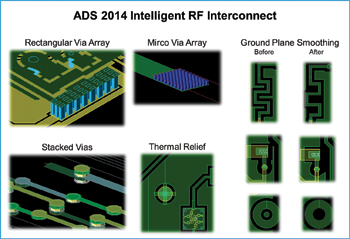
With ADS 2014, Agilent has created new Intelligent RF Interconnect to dramatically improve RF layout physical design and editing. New, single and multilayer smart interconnect structures like traces, vias and ground/signal planes make pin-to-pin routing and modifying RF layout interconnect efficient, intuitive and easy.
Vias can now be used as layout interconnect objects, not components. This means they can be used more efficiently in routing, and automatically resized during trace width insertion. Additionally, support for pinless vias eliminates schematic clutter.
And new planes allow designers to create a layer of copper to carry a particular signal on a printed circuit board (PCB). A plane can be generated as either a ground or signal plane using either an existing shape or by inserting or drawing a new polygon. The created planes support the following options:
- Clearance – Creates an appropriate clearance from shapes on different nets while connecting to shapes on the same net.
- Thermal Relief – Creates a thermal relief tie that helps take preventive action against overheating components.
- Smoothing Options – Enables you to smooth acute angles and remove notches.
- Plane Regeneration – Enables you to edit and regenerate the plane. For example, if you move the plane from one location to another, the shapes on the plane are automatically updated when the plane is regenerated.
Automated EM/Circuit Design Partitioning
One of the most well liked capabilities in today’s ADS is the Layout Lookalike component. With this capability, the designer is able to set up a circuit/EM co-simulation where the schematic models (e.g., SMT parts or active IC devices) are connected to a “lookalike” representation of the layout—an especially great feature for smaller designs.
However, for cases where the device-count grows to dozens or even hundreds—a common occurrence for larger ICs and PCB or laminate multi-technology designs—ADS 2014 now offers a new automated EM/Circuit Simulation Setup capability. The capability takes final, or interim, layout designs and automates all of the manual steps to set up an EM/Circuit co-simulation by removing SMD and active devices from the layout, inserting ports and replacing the parts in the schematic. The result is substantial time savings and elimination of manual errors, while including all of the EM effects of traces, vias and grounds for unmatched EM/circuit simulation result accuracy.
Wireless Verification Test Benches
Since ADS was first released, integrating standards-based modulated signal analysis has been a fundamental part of its architecture. Agilent Ptolemy with Wireless Libraries for Mobile Wireless (GSM, CDMA, 3GPP, LTE) and Wireless Networking (802.11, WiMAX) are the gold standard for verification of circuit designs to industry specifications.
The Wireless Verification Test Benches (VTB) in ADS 2014 provide circuit design verification solutions for the newest and most challenging multi-band, wide-bandwidth standards (LTE, LTE-A and 802.11ac) with a dramatically simplified user interface. These new VTBs and the underlying simulation technology are based on the Agilent EEsof SystemVue dataflow simulation technology and also allow system architects to develop custom VTBs for use by circuit designers in ADS.
The new simplified VTBs will be offered at a significantly lower cost than Agilent’s Ptolemy-based Wireless Libraries. And current Agilent Ptolemy customers will get the VTB Engine as part of the upgrades and support for their Agilent Ptolemy license. The VTB Engine will also be available separately and offered in a new low-cost ADS Verification bundle.
ADA Board Link
RF and microwave designs are often combined with non-RF circuitry on larger PCB boards. ADS offers integrated PCB flow solutions for flows with Cadence, Intercept, Mentor Graphics, Zuken and other PCB tools, based on the Agilent Intermediate File Format (IFF), ADS DFI and Dynamic Access for Mentor products, as well as a variety of artwork translators. The new ADS Board Link (ABL) in ADS 2014 is the next-generation solution for ADS integration with Enterprise PCB tools.
The ABL is a bi-directional interface for layouts, schematics and libraries between ADS and enterprise PCB tools to be imported into ADS. ABL also supports the import and export of libraries and technology information (e.g., units, resolution, layers, purposes, and substrates), as well as design data.
ABL enables RF schematic and layout designs started in ADS to be easily transferred to the enterprise PCB environment for integration into a larger design for floor planning; modified to accommodate physical design constraints; and then returned to ADS for verification—all while maintaining complete design integrity. Additionally, to debug a design that failed on the bench or for high-speed digital applications, an enterprise PCB layout design can be imported into ADS via ABL to perform post-layout EM analysis in ADS with little to no need for layout pre-processing before EM simulation.
The ABL design transfer between tools is high-fidelity and preserves all data and original objects. ABL is also architected to have significantly improved speed and capacity. As a result, major enterprise PCB tool vendors are now working with Agilent EEsof to offer support for ABL as soon as early 2014 with support for most major enterprise PCB tools by the end of 2014.
And there’s even more to look forward to in ADS 2014, including simulation support for the Agilent DynaFET Model, an advanced compact model of III-V FETs (GaAs and GaN) including electro-thermal and trapping effects; and simulation support for Agilent’s Nonlinear Vector Network Analyzer-measured X-parameter* models with memory effects, electro-thermal simulator enhancements, new DRC and LVS capabilities and technologies, and Silicon RFIC schematic interoperability with Cadence Virtuoso designs. And, for the growing number of high-speed digital designers using ADS, there are new high-speed digital capabilities in ADS 2014 as well.
ADS 2014 is currently in Beta testing and is expected to ship in the first quarter of 2014. Agilent EEsof invites customers to join its Early Access Program and to download and provide feedback on the Beta release. If interested, please contact your local application or technical support engineer.
*X-parameters is a trademark of Agilent Technologies Inc. The X-parameters format and underlying equations are open and documented. For more information on the use of this trademark, refer to X-parameters Open Documentation, Trademark Usage & Partnerships.
Agilent Technologies Inc.,
Santa Clara, CA,
www.agilent.com