
Increased pressure for low power, small form factor, low cost and reduced bill of materials in such radio applications as mobile communications has driven academia and industry to resurrect the direct conversion receiver. Long abandoned in favor of the mature superheterodyne receiver, direct conversion has emerged over the last decade or so thanks to improved semiconductor process technologies and astute design techniques. This article describes the characteristics of the direct conversion receiver and the issues it raises.
Very much like its well established superheterodyne receiver counterpart, first introduced in 1918 by Armstrong,1 the origins of the direct conversion receiver (DCR) date back to the first half of last century when a single down-conversion receiver was first described by F.M. Colebrook in 1924,2 and the term homodyne was applied. Additional developments in 1947 led to the publication of an article by D.G. Tucker,3 which first coined the term synchrodyne, for a receiver which was designed as a precision demodulator for measurement equipment rather than a radio. Another paper by Tucker in 19544 reports the various single down-conversion receivers published at the time and clarifies the difference between the homodyne (sometimes referred to as coherent detector) and the synchrodyne receivers -- the homodyne receiver obtains the LO directly (from the transmitter, for example), whereas the synchrodyne receiver synchronizes a free-running LO to the incoming carrier.
Over the last decade or so, the drive of the wireless market and enabling monolithic integration technology have triggered research activities on direct conversion receivers, which integrated with the remaining analog and digital sections of the transceiver, have the potential to reach the "one-chip radio" goal. Besides, it favors multi-mode, multi-standard applications and thereby constitutes another step towards software radio.
The present article refers to several recent publications5,6 which provide a thorough survey and insight, and display renewed interest in direct conversion receivers. Overcoming some of the problems associated with the traditional superheterodyne and being more prone to integration, DCR has nevertheless an array of inherent challenges. After a brief description of alternative and well-established receiver architectures, this article presents the direct conversion reception technique and highlights some of the system level issues associated with DCR.
TRADITIONAL RECEPTION TECHNIQUES
The Superheterodyne Receiver
The superheterodyne or heterodyne receiver is the most widely used reception technique and finds numerous applications from personal communication devices to radio and TV tuners. It has been used extensively and is well understood. It comes in a variety of combinations,7,8,9 but essentially relies on the same principle -- the RF signal is first amplified in a frequency selective low noise stage, then translated to a lower intermediate frequency (IF) with significant amplification and additional filtering, and finally down-converted to baseband with either a phase discriminator or straight mixer, depending on the modulation format. This technique is illustrated in the schematic of Figure 1.
|
|
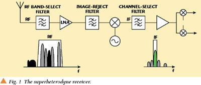
The use of a superheterodyne technique entails several trade-offs. Image rejection is a prevailing concern in this architecture. During the first down-conversion to IF, any unwanted activity at a frequency spaced at fIF offset from the LO frequency (fLO ) on the opposite side of fLO from the desired RF channel, will produce a mixing product falling right into the down-converted channel at fIF . In practice, a RF bandpass filter, usually a surface acoustic wave (SAW) device, is utilized to perform band selection ahead of the low noise amplifier (LNA), while a second filter follows the LNA to perform image rejection. If these filters are identical they share the burden of the two functions. But some amount of image rejection must follow the LNA, for without it, the LNA's noise figure will effectively double due to the mixing of amplified image noise into the IF channel. Instead of the RF SAW filter, other passive filtering technologies such as dielectric or ceramic resonators can also be featured. The higher the IF, the more relaxed the requirements on the cut-off frequency of the image reject filter. Once at the IF, the presence of an interfering signal in the vicinity of the channel mandates sharp filtering around the channel; this filtering is performed after the first mixer by the channel select filter, which is also often an IF SAW filter. Figure 2 shows this filtering process. Essentially, the exercise is that of a carefully engineered balance among several variables, including the rejection provided by the various filters, frequency planning and linearity of the active stages. Dual IFs provide additional room to maneuver with filter selectivity, but somewhat complicate the frequency planning.
|
|

The selectivity required of the two aforementioned filters (in terms of fractional bandwidth) makes them unsuitable candidates in the foreseeable future for integration, due to the low Qs of current silicon processes, and have to be implemented by bulky off-chip components. The IF channel filter in particular requires high Q resonators for its implementation -- the higher the IF, the lesser the filter's fractional bandwidth (that is, its ratio of bandwidth to center frequency), necessitating ever-higher Q. This high Q requirement is most commonly met by the use of piezoelectric SAW and crystal filters. This introduces additional constraints, as those filters often require inconvenient terminating impedances, and matching may impinge on such issues as noise, gain, linearity and power dissipation of the adjoining active stages. The narrower the fractional bandwidth, the more likely the filter's passband shape will exhibit an extreme sensitivity to variations in matching element values. Additionally, the specificity of the IF filter to the bandwidth of the signal and hence the standard used makes superheterodyne receivers unsuitable for multi-standard operation. Nonetheless, superheterodyne is known for its high selectivity and sensitivity.
Image-reject Receivers
Alternatively, by smart use of trigonometric identities, the image can be removed without the need of any post-LNA image-reject filtering. This is the principle of image-reject receivers8,10 , the first of which is the Hartley architecture, introduced in 192811 . It makes use of two mixers with their local oscillators in a quadrature phase relationship; this separates the IF signal into in-phase (I) and quadrature (Q) components. It then shifts the Q component by 90° before recombining the two paths, where the desired signal, present in both paths with identical polarities, is reinforced, while the image, present in both paths with opposite polarities, is cancelled out. The dual of the Hartley architecture, known as the Weaver image-reject receiver,12 achieves the relative phase shift of one path by 90° by the use of a second LO enroute to another IF or to baseband. The same result is achieved. However, the reliability of these receivers heavily depends on the accuracy of the I/Q paths, that is, the gain and phase imbalance between the two branches. Figures 3 and 4 show diagrams of the Hartley and Weaver image-reject architectures, respectively (high frequency mixing products are removed by low-pass filtering -- not shown on figures).
|
|
|
|
|
|


Low IF Single Conversion Receiver
Low IF single conversion, shown in Figure 5, is an offspring of the DCR. Its main purpose is to protect the receiver from all the DC-related problems that pertain to DCR, while retaining the DCR's benefit of elimination of high Q IF filters. As its name indicates, instead of directly converting the signal to baseband, the LO is slightly offset from the RF carrier, typically one to two channels. The low IF means that the fractional bandwidth of the IF bandpass filtering is large, making it possible to implement it with low Q components. The IF SAW or crystal filter needed in the high IF case can be replaced with an active RC filter or other filter suitable for low frequency operation, that is also conducive to silicon integration. The low IF signal may be translated to baseband through another mixer, or preferably, in the digital domain following analog-to-digital (A/D) conversion. Of course, this comes at the expense of faster and higher resolution A/D converters. If the IF frequency is equal to only one or two channel widths, then it is not possible to provide image rejection at RF, as the RF filter must be wide enough to pass all channels of the system. In this case, all image rejection must come from the quadrature down-conversion to the low IF, which itself resembles the Hartley architecture, once the baseband conversion is added.
Wideband IF with Double Conversion
This architecture, shown in Figure 6, is very similar to the superheterodyne configuration. In this case, the first mixer utilizes an LO that is at a fixed frequency, and all channels in the RF band are translated to IF, retaining their positions relative to one another. The second mixer utilizes a tunable LO, thus selecting the desired channel to be translated to baseband. A subsequent lowpass filter suppresses adjacent channels.
DIRECT CONVERSION RECEIVERS
Direct conversion reception, shown in Figure 7, and also referred to as homodyne, or zero-IF, is the most natural solution to receiving information transmitted by a carrier. However, it has only been over the past decade or so that this type of reception has found applications other than pagers.13 Direct conversion reception has several qualities which makes it very suitable for integration as well as multi-band, multi-standard operation, but there are severe inherent obstacles that have for a long time kept it in the shadow of the superheterodyne technique.
|
|

First, the problem of the image has been eliminated, since the IF is zero and the image to the desired channel (for all but single-sideband signals) is the channel itself. Then, only one local oscillator is required, which means only one phase noise contribution. The need for the bulky off-chip filters is consequently removed. Filtering now only occurs at low frequencies (baseband) with some amplification, which means less current consumption than at higher frequencies (to drive device parasitics), fewer components and lower cost. Practically, however, strong out-of-band interference or blocking signals may need to be removed prior to down-conversion in order to avoid desensitizing the receiver by saturating subsequent stages, as well as producing harmonics and intermodulation terms which will then appear in the baseband. Such a filter may be placed after the LNA for example. DCR, however, brings its own set of issues.
DC Offsets
In direct conversion, as the signal of interest is converted to baseband very early in the receive chain, without any filtering other than RF band-selection, various phenomena contribute to the creation of DC signals, which directly appear as interfering signals in the band of interest, as shown in Figure 8.
|
|

The LO may be conducted or radiated through an unintended path to the mixer's RF input port, thus effectively mixing with itself, producing an unwanted DC component at the mixer output. Worse still, this LO leakage may reach the LNA input, producing an even stronger result. This effect presents a high barrier against the integration of LO, mixer and LNA on a single silicon substrate, where numerous mechanisms can contribute to poor isolation. These include substrate coupling, ground bounce, bond wire radiation, and capacitive and magnetic coupling.
Conversely, a strong in-band interference signal, once amplified by the LNA, may find a path to the LO-input port of the mixer, thus once again producing self-mixing.
Some amount of LO power will be conducted through the mixer and LNA (due to their non-ideal reverse isolation) to the antenna. The radiated power, appearing as an interferer to other receivers in the corresponding band, may violate emissions standards of the given system. It is important to note that since the LO frequency is inside the receive band, the front-end filters do nothing to suppress this LO emission. Additionally, the radiated LO signal can then be reflected by buildings or moving objects and re-captured by the antenna. This effect, however, is not of significant importance compared to the aforementioned LO self-mixing and blocking signal self-mixing.
The leakage of LO or RF signals to the opposite mixer port is not the only way in which unwanted DC can be produced. Any stage that exhibits even-order nonlinearity will also generate a DC output. This is covered in more detail later.
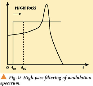
Whether or not the DC product will desensitize the receiver depends on the type of system. Obviously it is preferable to AC couple at the mixer output to eliminate the DC. Some modulation schemes, such as frequency shift keying (FSK) used in paging applications, show little degradation if low frequency components of the spectrum are filtered out, as shown in Figure 9. However, other modulation schemes present a peak at DC, and capacitive AC coupling will lead to significant information loss, hence considerably degrading the bit error rate (BER). In TDMA systems such as GSM, there is no significant low frequency spectral peak, but it still becomes impossible to AC couple. This is because of the conflicting requirements on an AC coupling capacitor in a TDMA system -- the capacitor must be large enough to avoid causing a wide notch at DC, but it must be small enough that all transients settle out upon power-up of the receiver (every frame) before data reception begins.
|
|
In TDMA receivers that cannot be AC coupled, the idle timeslot (just before reception) can still be put to good use by storing the value of the offset in a capacitor and then subtracting it from the signal path during the burst. This is exactly the same method that is normally used to correct DC offsets occurring at the second mix of superheterodyne TDMA receivers, where this mix goes to baseband (in that case the only problem causing DC is LO self-mixing). In this method the value of DC produced by the receiver is obtained in a pre-measurement prior to the receive burst. It is important when using this method that the signal path prior to the mixer be opened during the DC pre-measurement to prevent any large blocking signals from affecting the result. Variable or wandering offsets are most often induced by blocking signals, which can appear at any time. These offsets cannot be corrected by the measurement-and-subtraction process, because the blocking signals may appear during the measurement and not during the burst, or vice-versa. For blocking-induced DC, the most effective measures are the elimination of self-mixing paths and the maximizing of linearity to prevent the DC to begin with. Failing these, there is still the possibility of DC correction after-the-fact in the digital signal processing occurring at baseband.
Digital signal processing (DSP) techniques can be used to remove the DC offset in TDMA systems in a way that cannot be duplicated in the analog domain -- a full timeslot of the received signal can be buffered, the mean of which is determined and then removed from each data point of the signal. The resulting signal has zero mean. For systems such as GSM, an unwanted result of this is that any DC that is part of the signal will be lost, but the typical effect of this is minimal. Figure 10 illustrates the use of such a method for a typical GSM receiver. This technique can be further refined by tracking the mean over portions of the burst, allowing the detection of sudden interferers or blockers and cancelling their DC product only where it occurs. Careful layout can also improve isolation.
|
|

Nonlinearities
As mentioned previously, another problem for the DCR is nonlinearity. Just as with the superheterodyne receiver, the DCR exhibits spurious responses. For the superheterodyne these occur at RF input frequencies where N(RF) ± M(LO) = IF, while for the DCR they occur where N(RF) M(LO) = 0. When a blocking signal's carrier falls on one of these spurious frequencies, the signal is translated to baseband with an attendant shift in its bandwidth, dependent on the spurious order.
More importantly, however, large blocking signals also cause DC in the direct conversion receiver, whether on a spurious frequency or not. The DC is produced at the mixer output and amplified by the baseband stages. It is due primarily to second-order nonlinearity of the mixer, characterized by the second-order intercept point (IP2) and second-order intermodulation (IM2). It can be alleviated by extremely well-balanced circuit design. However, the mixer and LNA used to require a single-ended design because the antenna and a hypothetical preselect filter were usually single-ended.
In most systems, the third-order intermodulation is of importance as it usually falls in-band, in the vicinity of the signals of interest, and is characterized by the third-order intercept point (IP3). In direct conversion, second-order nonlinearity becomes critical, as it produces baseband signals, which now appear as interfering signals in the down-converted desired signal. IM2 is measured by the IP2. IP2 is defined in the same manner as IP3, as shown in Figure 11. Either a two-tone, or single tone test can be performed, and the IP2 is defined by extrapolating the low frequency beat tone in the former or the DC component in the latter, until it intercepts the fundamental curve. To illustrate the case of a single tone test, the input signal is
|
|

x(t) = Acost(ωt).
Assuming a nonlinearity modeled by a polynomial
It can be seen that the DC component due to the second-order nonlinearity is growing with twice the slope of the fundamental on a logarithmic scale. At the intercept point,
Due to the doubled slope of the second-order product,
IIP2 = Pin + Δ with Δ = Pout IM2
Noise
Low frequency noise14 becomes a great concern in a DCR, as significant gain is allocated to baseband stages after the mixer. Weak signal levels of a few millivolts in baseband are still very vulnerable to noise. This requires stronger RF stage gain to alleviate the poor noise figure of baseband blocks, but of course this must be traded against the linearity problems, just described, that accompany higher RF gain.
Flicker noise, or 1/f noise, is the major baseband noise contributor. Associated with a flow of direct current, it has a spectral response proportional to 1/f. In RF circuits, 1/f noise tends to be modulated onto the RF signal, and in the case of a mixer with baseband output, 1/f noise sees especially high conversion gain. In practice, flicker noise becomes an issue for MOS devices more than bipolar, and is modeled as a voltage source in series with the gate. 1/f noise complicates the use of MOS transistors for RF circuits, since the main method of reducing it in MOS is to increase the transistor's size, which increases the device capacitance, adversely affecting RF gain. For this reason it is preferable to use bipolar transistors for DCR mixer designs. In the first baseband stages after the mixer, it becomes possible to use MOS devices, as the transistor-size trade-off is feasible at low frequencies.
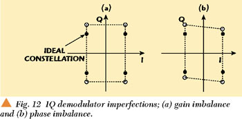
I/Q Mismatches
Due to the high frequency of the LO, it is not possible to implement the IQ demodulator digitally. An analog IQ demodulator exhibits gain and phase imbalances between the two branches, as well as the introduction of DC offsets. Such imperfections distort the recovered constellation. Assuming  and
and  are the amplitude and phase mismatch, respectively, between the quadrature ports of the demodulator, and the complex signal incident upon it have in-phase and quadrature components I and Q, then
|
Iout |
= |
(Icos(ωt) + Qsin(ωt)) |
|
Qout |
= |
(Icos(ωt) + Qsin(ωt)) |
 2cos(ωt)
Filtering out the high frequency terms yields
|
Iout |
= |
I |
|
Qout |
= |
(1 + |
Figure 12 shows how this affects a given constellation diagram. In DCR systems, however, the IQ matching is not as critical as in image-rejection architectures. Rather, it is only important insofar as the accuracy of the modulation is concerned.
|
|
Analog and digital (DSP based) calibration and adaptation methods have been described so as to correct for these imbalances.15
CONCLUSION
The direct conversion receiver is an attractive yet challenging receiving technique. It has been successfully applied to devices such as pagers, mobile phones, PC and internet wireless connectivity cards, and satellite receivers, etc. in a variety of process technologies and increasing integration levels. It is poised to appear in many more applications in the near future.
ACKNOWLEDGMENTS
The authors would like to thank Darioush Agahi and Morten Damgaard of Conexant Systems for their valuable input to this article. *
References
1. L. Lessing, "Man of High Fidelity: Edwin Howard Armstrong, a Biography," Bantam Books, New York, 1969.
2. F.M. Colebrook, "Homodyne," Wireless World and Radio Rev., 13, 1924, p. 774.
3. D.G. Tucker, "The Synchrodyne," Electronic Engng, 19, March 1947, pp. 7576.
4. D.G. Tucker, "The History of the Homodyne and the Synchrodyne," Journal of the British Institution of Radio Engineers, April 1954.
5. A.A. Abidi, "Direct-conversion Radio Transceivers for Digital Communications," IEEE Journal of Solid-state Circuits, Vol. 30, No. 12, December 1995.
6. B. Razavi, "Design Considerations for Direct-Conversion Receivers," IEEE Transactions on Circuits and Systems-II: Analog and Digital Signal Processing, Vol. 44, No. 6, June 1997.
7. S.J. Franke, "ECE 353 Radio Communication Circuits," Department of Electrical and Computer Engineering, University of Illinois, Urbana, IL, 1994.
8. B. Razavi, "RF Microelectronics," Prentice Hall, Upper Saddle River, NJ, 1998.
9. J.C. Rudell, et al., "Recent Developments in High Integration Multi-standard CMOS Transceivers for Personal Communication Systems," International Symposium on Low Power Electronics and Design, 1998.
10. J.C. Rudell, "Issues in RFIC Design," lecture notes, University of California Berkeley/National Technological University, 1997.
11. R. Hartley, "Single-sideband Modulator," U.S. Patent No. 1666206, April 1928.
12. D.K. Weaver, "A Third Method of Generation and Detection of Single Sideband Signals," Proceedings of the IRE, Vol. 44, December 1956, pp. 17031705.
13. I.A.W. Vance, "Fully Integrated Radio Paging Receiver," IEE Proc., Vol. 129, No. 1, 1982, pp. 26.
14. P.R. Gray and R.G. Meyer, "Analysis and Design of Analog Integrated Circuits," Third edition, John Wiley & Sons, New York, 1993.
15. J.K. Cavers and M.W. Liao, "Adaptive Compensation for Imbalance and Offset Losses in Direct Conversion Transceivers," IEEE Transactions on Vehicular Technology, Vol. 42, November 1993, pp. 581588.
Ashkan Mashhour received his Diplôme d'ingénieur from ENST Bretagne, France, and his MSc from University College London, UK, both in 1997. He then joined Nokia Networks, Camberley, UK, where he worked as a RF design engineer. His research involved the development of new RF/DSP technologies and linear transceiver architectures for future generation base stations. He is currently with Conexant Systems, Newport Beach, USA. He can be reached at: ashkan.mashhour@conexant.com.
William Domino received his BSEE degree from the University of Southern California in 1979, and his MEng degree from the California State Polytechnic University, Pomona, CA, in 1985. He joined the Collins Radio business of Rockwell International, Newport Beach, USA, in 1979, where he developed electromechanical IF filter models, design techniques and production processes. Currently a principal RF systems engineer with the Wireless Systems business of Conexant Systems, also in Newport Beach, USA, he has been involved in the design and development of integrated transceiver architectures for IS-136, Mobitex packet radio and GSM handsets. He can be reached at: william.domino@conexant.com.
Norman Beamish earned his BEng and his PhD from University College Dublin, Ireland, in 1989 and 1994, respectively. His PhD research was in the field of DSP and digital communications with a particular interest in the equalisation of channels containing nonlinearities. He held a research engineering position at Teltec, Ireland, from 1994 to 1995. He is currently a principal engineer with Conexant Systems, Newport Beach, USA, where his primary interests are in the area of wireless baseband systems, particularly for GSM, 3G cellular systems and spread spectrum communications. He can be reached at: norman.beamish@conexant.com.