In-phase/quadrature-phase (I/Q) errors in the implementation of a digital predistortion (DPD) system based on a direct-conversion structure have proven to be a limiting performance factor in modern communication systems. This work presents a method of time domain compensation (TDC) for frequency-dependent channel imbalances in wideband DPD systems. Compared with the widely used frequency domain compensation method, this method has lower computational complexity. Experimental results show that this method improves transceiver loop normalized mean squared error (NMSE) for 20 and 60 MHz Long Term Evolution (LTE) signals by 10.9 and 11.3 dB, respectively. Adjacent channel power ratio (ACPR) is improved by more than 6 and 8 dB, respectively.
The RF power amplifier (PA) is a major component in wireless communication systems; however, PA intermodulation distortion leads to signal errors and spectrum expansion. To solve the problem, both analog and digital predistortion have been employed.1,2 DPD, with the advantages of convenient implementation, flexibility and adaptability, has become the preferred approach.
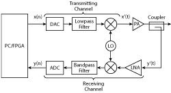
Figure 1 DPD system with an imperfect transceiver loop.
Figure 1 is a block diagram of a DPD system with an imperfect transceiver loop. Numerous DPD models have been presented,3 but they do not consider the impact of I/Q imbalance in the transceiver. Anttila et al.4 noted that I/Q imbalance seriously affects DPD performance, and they presented a new DPD structure for reducing I/Q imbalance in direct-conversion radio transmitters. Kim et al.5 described a joint DPD method for compensating PA nonlinearity and I/Q imbalance; however, only frequency-independent I/Q imbalance was considered. Rampa6 introduced a frequency-dependent I/Q imbalance compensation scheme, but considered only transmitter distortion. Rawat et al.7 used a hybrid RF/DPD structure based on a lookup table to compensate for I/Q imbalance, but it needed a large amount of storage space.
In this work, we focus on PA nonlinearity and frequency-dependent I/Q imbalance in the implementation of a broadband DPD platform that compensates for imbalance from both the transmitter and receiver. Through measurements of the signal with different bandwidths, the method of TDC described here works well in systems with significant I/Q distortion.
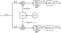
Figure 2 Typical direct-conversion receiver.
NONLINEAR DISTORTION MODEL
Figure 2 shows the block diagram of a typical direct-conversion receiver to illustrate the following discussion of I/Q receiving channel imbalance model extraction and PA nonlinear modeling.
Channel I/Q Imbalance Model
Without loss of generality, the following derivation assumes that the I/Q imbalance is frequency independent. Also assume that the I/Q imbalance is caused by local oscillator (LO) imbalance in the I/Q path. Figure 2 shows the baseband equivalent signal model for I/Q imbalance, which can be written as1
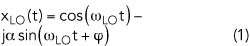
Using Euler’s formula
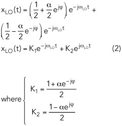
and α is the amplitude imbalance and φ is the phase imbalance.
Actually, Equation 2 takes into account the bandpass filter (BPF) imbalance as well. Assuming that the received signal is ideal, where xI(n) and xQ(n) are the real and imaginary parts, the complex baseband signal is
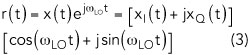
In the receiver, the ideal complex baseband signal through the BPF and mixer can be written as
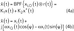
and we have
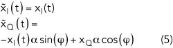
for which the matrix form is
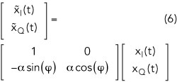
If α and φ are extracted from Equation 1, the amount of compensation for the channel can be estimated. In most of the literature, compensation is done with a mirror image signal. Alternatively, we use digital pre-compensation in the I and Q paths.
PA Model Extraction
The nonlinear model of a PA is also key to DPD performance. However, because much has been written about this in the literature,8-10 it is not the focus of our work. We use the first-order dynamic derivation reduction (DDR) model to describe PA nonlinearity, which can be written as
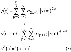
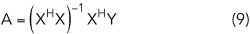
where p denotes the order of nonlinearity and M is the memory length. x(n) and y(n) are the input and output of the PA, respectively. From Equation 7, the matrix form is

where X is the PA input vector and Y is the PA output vector. A represents the coefficients vector of the PA, which can be obtained with the least squares algorithm. For example,