
Ever since the 1940s, the design of radar systems has been subject to continuous innovation and experimentation. Today, radar systems use technology ranging from ultra-wide bandwidths (UWB)1 to phased arrays and even passive radar. Some of the emerging technologies under investigation from the radar community include: cognitive radar2, waveform diversity3 and compressive sensing.4 In addition, multifunction radars, such as DMPAR,5 can be employed for meeting the requirements of multiple scenarios and challenges.
In the defense industry, there is a continuous contest between radar and electronic support measures (ESM) systems. Radar scientists are looking for new technologies that will improve the low probability of intercept (LPI) properties of radar and prevent ESM receivers from detecting and classifying signals transmitted by radar. In these applications, the requirement of ambiguity-free radar has increased interest in noise or pseudo-noise radar systems6 that use digital transmitters and receivers with hundreds of MHz of instantaneous bandwidth.
UWB radar technology remains an attractive technology because of its ability to increase obstacle detection and tracking resolution of traditional radar systems. More importantly, UWB systems do this while spreading power over a wider signal bandwidth. As a result, they inherently transmit a lower power in any narrow band and reduce the likelihood of detection. IEEE Standard 6867 defines ultra-wideband as any signal that either occupies more than 25 percent of the bandwidth of the carrier (called ‘percentage bandwidth’) or has a bandwidth greater than 500 MHz.
This article will discuss some of the design and test challenges associated with UWB radar systems with a focus on system verification and RF testing, trends in radar architecture, approaches to system design and prototyping, and typical RF measurements.
Figure 1 Software defined radar systems.
EVOLUTION TO SOFTWARE-DEFINED ARCHITECTURES
As the design of modern radars has adopted an increasingly sophisticated software-defined architecture, advanced signal processing algorithms have become an essential element of modern radar systems. Figure 1 illustrates a general block diagram of a modern radar system. In this figure, high sample rate digital-to-analog converters (DAC) and analog-to-digital converters (ADC) support wide input signal bandwidth. In microwave radar systems, these components enable wide instantaneous bandwidths of the radar system. In some cases, use of high sample rate DACs and ADCs also enables the design and deployment of direct sampling transmitters and receivers for L-Band radars.
In phased array radar systems, having multiple channels of the analog signal conditioning and ADCs/DACs is a key requirement. In these applications, providing tight synchronization between these elements using low-phase noise local oscillators and sampling clock sources is crucial to ensuring a high degree of system performance.
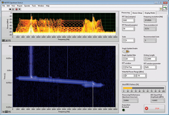
Figure 2 Analyzing radar chirp on a real-time spectrum analyzer.
In addition to synchronization between channels, today’s software defined radio systems require synchronization within elements of the processing chain, including DDCs, DUCs and channelization algorithms. The ultra-wideband architecture use of a large number of channels, in conjunction with high sampling rate converters, produces an immense amount of data. As a result, transferring this data (often multiple gigabytes/sec) introduces additional challenges in the system architecture design and verification.
The software-defined approach to radar system design is an important enabling technology in modern radar system design because it allows the engineers and scientists to continually evolve radar systems with new waveforms and architectures. As a result, engineers are increasingly adopting software defined radio platforms as a design tool for next-generation radar algorithms.
DESIGNING MODERN RADAR SYSTEMS
The instantaneous bandwidth requirements of modern UWB radar systems add considerable difficulty to the challenges of designing and prototyping modern radars. For example, with signal bandwidths of up to 500 MHz, the data associated with the single physical channel ranges from 2 to 4 GB/s – depending on ADC and DAC resolution. Not only do these extremely high data rates present a significant challenge in the design of the deployed radar, but they also introduce significant challenges when prototyping. In order to better understand these challenges, it is worth explaining the typical design process used in the design of a radar system and how engineers are dealing with the large amount of data that modern radar systems produce.
Figure 3 Architecture of a simplified two-channel RF signal analyzer.
Historically, radar systems had typically been designed and integrated by a small team of hardware engineers. However, today’s increasingly complex, software-defined radar systems require a mix of software, digital and analog designers. As a result, engineers face an increasing need for a highly integrated tool chain that enables them to prototype radar systems early during the design process.
An increasingly common approach to radar system verification and prototyping is the use of software defined radio technology to design and test the signal processing algorithms used in modern radar systems. When developing such systems, engineers are tasked with the challenge of designing and testing signal processing algorithms, often before the front end design is complete. An increasingly common approach to radar validation is to use instrumentation as the radio front end to validate the behavior of signal processing.
VALIDATING RADAR SIGNAL CHARACTERISTICS
Validating radar subsystems or building prototypes using instrumentation requires extremely wideband instrumentation. Not only can engineers use instrumentation to validate the behavior of complex radar signals, but they can also use it to emulate the behavior of the radar itself at either baseband or RF frequencies.
For example, consider the use of real-time spectrum analysis tools to validate the creation of a hopped or chirp waveform. At baseband frequencies, one can use an IF digitizer such as the NI PXIe-5624R IF with up to 1.7 GHz of analog bandwidth with a digital downconverter capable of up to 800 MHz of instantaneous bandwidth. Engineers can use this instrument or similar ones as either as an IF digitizer connected to existing RF front ends or as a direct sampling digitizer in L-Band radar systems. At RF frequencies, engineers can use a vector signal analyzer (VSA) such as the NI PXIe-5668R VSA that has more than 500 MHz of RF bandwidth at frequencies up to 26.5 GHz. As illustrated in Figure 2, both of these instruments offer real-time spectrum analysis capabilities that execute a wideband FFT on samples. As a result, the behavior of a radar pulse can be validated using displays such as the persistence plot or the real-time spectrum analyzer.
Figure 4 Typical radar pulse measurements.
MULTI-CHANNEL ANALYSIS
A second key verification technique of advanced UWB radar systems is the use of multi-channel instruments to verify radar behavior. Modern radar systems, that often use active electronic scanned array (AESA) technology, are increasingly utilizing multi-channel architectures. Common multi-channel implementations include phased-array and multiple-input multiple-output (MIMO) radar systems with co-located antennas.
Although the two approaches use similar radio configurations, there is a distinct difference between phased-array and MIMO radar systems. A phased-array radar transmits scaled versions of the same waveform whereas a MIMO radar system transmits different waveforms from different transmit antennas in order to achieve a large virtual array size.2 Due to the constraints of MIMO radar design, several alternate transmission schemes have attracted much interest including: FDMA, TDMA, randomized TDMA, Doppler DMA and slow-time CDMA.
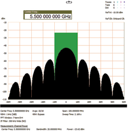
Figure 5 Main power lobe of a 50 ns pulse is contained within a bandwidth of 20 MHz.
The complexity of multi-channel radar systems creates significant challenges for engineers tasked with verifying the performances of the radar system. In fact, phase-coherent RF signal acquisition systems require sophisticated synchronization technology to ensure that each downconverter/digitizer shares all timing signals, including local oscillators (LO), sample clocks and start triggers. As we observe in Figure 3, a two-channel RF signal analyzer requires each channel to share a common LO.
Modular instruments such as PXI have become an increasingly popular approach to testing multi-channel radar systems because of their native support of tight channel-to-channel synchronization. For example, up to 16 IF channels of a digitizer can easily be synchronized in a single PXI chassis. At RF frequencies, modular PXI RF signal analyzers feature the ability to share local oscillators between each channel. As a result, using multiple PXI chassis, it is possible to synchronize 2, 4, 8 or even more RF channels using the native synchronization characteristics of PXI.
RADAR TESTING
A final challenge of modern UWB radar testing is associated with the bandwidth requirements of wideband pulsed transmissions. Today’s radar systems can require extremely wide bandwidths either through extremely short pulse widths or through pulse compression. Common radar pulse measurements include rise time, fall time, overshoot and pulse width. Although extremely short pulses with a shorter pulse repetition interval (PRI) improve radar resolution (at the expense of range), they inherently require RF signal analyzers with very wide instantaneous bandwidth. All of these measurements, illustrated in Figure 4, are performed using the zero span mode of an RF signal analyzer, which displays power as a function of time.
Pulsed radar signals are typically characterized by a sinc function in the frequency domain. As a result, when measuring extremely wide pulses, wide instantaneous bandwidth is required to accurately measure rise time. In Figure 5, observe the frequency domain of a 50 ns pulse. The main power lobe of a 50 ns pulse is contained with 20 MHz of bandwidth. However, substantial power exists in each of the adjacent side lobes. Thus, accurately measuring pulse time also requires capturing the side lobes as well. A general rule of thumb for measuring pulse rise time is that the instrument’s instantaneous bandwidth must be three times wider than 1/rise time.
Figure 6 Time domain of a 50 ns pulse using 500 MHz of instantaneous bandwidth.
For example, in order to measure pulse rise times as low as 6 ns, the required instrument instantaneous bandwidth would be 3/(6 ns) or 500 MHz. In Figure 6, we observe the same 50 ns pulse from Figure 5 in the time domain using 500 MHz of instantaneous bandwidth. This configuration shows the rise time of 20 ns given an extremely wide bandwidth and short time-domain resolution of 2 ns.
In addition to measuring short pulse rise times, engineers are increasingly using wideband instruments to test the effectiveness of pulse compression algorithms. Pulse compression techniques such as an FM chirp, shown in Figure 7, can be an extremely effective mechanism to spread transmission power over an extremely wide bandwidth. However, the use of increasingly wide modulation bandwidths for modern pulse compression techniques can often push the measurement limits of modern RF signal analyzers.
For example, because an FM chirp spreads signal power over frequency, it is important to measure power variation over the duration of the pulse to ensure that transmitted power is not frequency dependent. In a traditional spectrum analyzer in swept mode, approximate pulse power is measured by averaging spectrum over a large number of traces and scaling the measured power according to the duty cycle of the transmission.
However, modern wideband vector signal analyzers often allow engineers to capture an entire wideband pulse in a single acquisition. Using this technique, engineers can measure power versus frequency and time more accurately, as well as measure additional pulse characteristics such as the linearity of an FM chirp or characterize LPI signals.
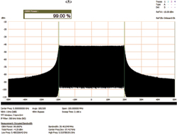
Figure 7 Example FM chirp occupying approximately 40 MHz of bandwidth.
CONCLUSION
The needs and challenges of the design and verification of UWB radar systems require engineers to use sophisticated tools for radar design and test. Today, engineers are using a combination of advanced software and hardware that includes complex scenario generators, wideband signal analyzers and multi-channel modular instruments. These tools allow engineers to quickly prototype and validate advanced radar systems using a common set of hardware.
References
- Mark E. Davis, Frequency Allocation Challenges in Ultra-Wideband Radars, July 2013, s.l. : IEEE A&S System Magazine, 2013.
- Joseph R. Guerci, Cognitive Radar: The Knowledge-aided Fully Adaptive Approach. s.l.: Artech House, 2010.
- Fulvio Gini, Antonio De Maio, Lee Patton, Waveform Design and Diversity for Advanced Radar Systems. s.l. : IET, 2012.
- Etgar Israeli, Shahar Tsiper, Deborah Cohen, Eli Shoshan, Alex Reysensen and Yonina C. Eldar. Sub-Nyquist Cognitive Radio System. IEEE ICASSP Conference- Show and Tell, [Online] May 2014, [Cited: 2014 13-May], www.icassp2014.org/files/ST/1569913589%20-%20A%20Sub-Nyquist%20Radar%20Prototype.pdf.
- Kuschel, Heniner, Deployable Multiband Passive/Active Radar for Air Defense (DMPAR), Aerospace and Electronic Systems Magazine, IEEE, September 2013, Vol. 28, 9.
- Kulpa, Krzysztof, 2013. Signal Processing in Noise Waveform Radar. s.l.: Artech House, 2013.
- IEEE Standard 686 for Radar Definitions.