
A compact microstrip, tri-band, bandpass filter (BPF) using short-circuited stub-loaded stepped impedance resonators (SIR) is proposed in this article. First, the hairpin SIR generates a dual-mode, dual-band response by loading a short-circuited stub. The nature of the proposed resonator is investigated through the even-odd mode analysis. Second, a pair of extended feedlines adds a new transmission path to produce the third passband. The proposed SIR and extended feedlines are folded and thus result in a compact size for the filter. Three passbands are designed to operate at 1.57, 3.5 and 5.2 GHz, respectively. All the theoretical analysis has been successfully verified by experiment results.
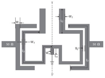
Figure 1 Schematic of the dual-band dual-mode, SIR loaded with a short-circuited stub.
In recent years, the rapid development of multiple band operations for wireless communication applications has attracted the attention of many researchers. Compact triple-band bandpass filters have been studied extensively as a key circuit block in tri-band wireless communication systems.1-3 In multiband communication systems, the bandpass filter (BPF) plays an important role in the RF front-end of the communication system. To design a multiband BPF, two-section stepped impedance resonators (SIR) have been used as a building block.4 However, this results in a larger circuit size and a more complex BPF configuration. A triple-band BPF was constructed using conventional λ/4 SIRs.5 Chu and Lin presented a triple-section SIR for triple-band BPF design.6 Design techniques for triple-band filters based on several parallel- and cross-coupled resonators have been used, but they are still challenging to the designer because it is difficult to fit the specifications at three bands due to the limited degrees of freedom in the design parameters.
In this article, a triple-band filter is proposed using a short-circuited stub-loaded SIR, which is explained by an even-odd mode method. The triple-band filter has a small size, only extending a set of feedlines without increasing the circuit size. Simulations and measurements are given to prove this improved structure of the filter.
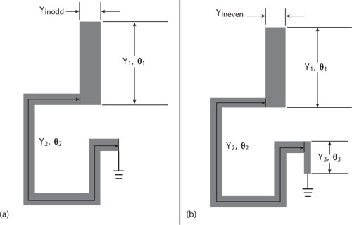
Figure 2 Equivalent circuits (a) odd-mode and (b) even-mode.
Dual-Mode Dual-Band Short-Stub Loaded SIR
As shown in Figure 1, a compact microstrip BPF is composed of the proposed dual-mode, dual-band short-circuited stub-loaded SIR and two transmission lines with characteristic impedance of 50 Ω, which act as input and output ports.7 Since the proposed SIR is a symmetrical structure, even-odd mode theory can be adopted to implement it and its equivalent circuits are described in Figure 2. For the odd and even mode excitation, the symmetry plane TT" is considered as a short end and an open end, respectively. The input admittance Yineven, Yinodd of the even- and odd-mode resonator can be extracted:
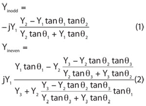
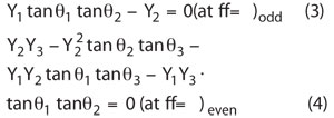
According to the resonance condition of Yinodd = 0 and Yineven = 0, the resonant frequencies can be expressed as:
where Yi (i = 1, 2, 3) are the characteristic admittances of the widths Wi (i = 2, 3, 4), and θi (i = 1, 2, 3) are electrical lengths of the three sections of the length Li (i = 2, 3, 4), respectively.
From Equation 3, it can be seen that the odd-mode resonant frequencies (fo1, fo2) are determined by θ1, θ2, Y1 and Y2. Thus, by reasonably designing these parameters, the resonant frequencies fo1 and fo2 are approximately allocated in the first and second passbands, respectively. Also, the total electrical length θ of the odd mode resonator is defined:
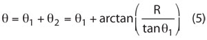
where R is the impedance radio Y2/Y1. The relation between the normalized total electrical length θ versus θ1 with R as a parameter is shown in Figure 3. There are various solutions for θ, which are dependent on the choice of R and θ1.8 From the figure, it can be seen that a compact size may be obtained by having an appropriated θ1 and small impedance ratio R.
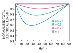
Figure 3 Normalized total electrical length (θ) with varied θ1.
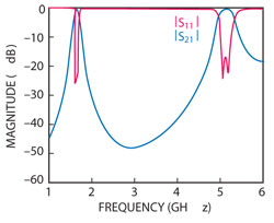
Figure 4 Simulated frequency responses of the proposed SIR.
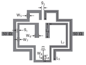
Figure 5 Schematic view of the proposed tri-band BPF.
From Equation 4, the even-mode resonant frequencies depend exclusively on θ3, Y3. Furthermore, as the electrical length θ3 decreases, the even-mode resonant frequencies (fe1, fe2) will correspondinglygetclose to the odd-mode resonant frequencies (fo1, fo2), whereas the odd-mode resonator frequencies (fo1, fo2) remain stationary. Hence, the four resonant frequencies can be allocated within the desired passbands to realize a dual-band, dual-mode filter by reasonably choosing the parameters of SIR and short stub, respectively.
To verify the theoretical analysis, a dual-mode dual-band filter has been designed, which works in the GPS band (1.57 GHz) and the WLAN band (5.2 GHz). The proposed filter is simulated by Ansoft HFSS 10. The substrate has a thickness of h = 0.8 mm and a relative dielectric constant of εr= 4.5. Its dimensions are as follows: L1 = 14.45 mm, L2 = 5 mm, L3 = 19.05 mm, L4 = 1.056 mm, W1 = 0.65 mm, W2 = 1.2 mm, W3 = 0.6 mm W4 = 1 mm and g0 = 0.2 mm. The simulated frequency responses are shown in Figure 4. It is clearly observed that the center frequencies are generated at 1.57 and 5.2 GHz. The return losses within the two passbands are below 20 dB.
Tri-Bands BPF Design and Results
Based on the dual-mode, dual-band discussion, a triple bandpass response can be achieved by adding an additional transmission path at a different resonant frequency. In this article, the extended feedlines are folded outside to produce the third bandpass, without significantly increasing the circuit size. The schematic of the proposed tri-band BPF is shown in Figure 5. Besides, the resonator frequency of the extended feedlines can be independently tuned to the desired passband (WiMAX, 3.5 GHz). It is approximately given by:
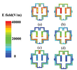
Figure 6 Simulated electric field distribution at resonant frequencies (a) fo1, (b) fe1, (c) fo2, (d) fe2, (e) and (f) for the two poles of the extended line.
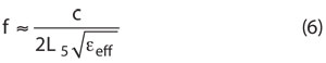
where L5 is the length of the extended feedlines. The electric field distributions at the resonant frequencies of the tri-band BPF are illustrated in Figure 6. It is evident that the odd modes have an electric field distribution similar to that of the single SIR. Hence, the tapping point of the short stub is actually a virtual ground for the odd modes. As a consequence, the short stub does not affect the odd-mode characteristic, including its resonant frequencies. On the contrary, the short stub can affect the even characteristic, which can be demonstrated in the electric field distribution at even-mode frequencies. That is the reason why the change of θ3 controls the resonant frequencies of the even mode. Figures 6 (e) and (f) show that the electric field is mainly concentrated in the extended feedlines.
The proposed filter is fabricated on the same substrate as mentioned previously. The physical dimensions of the filter are chosen as follows: L5 = 21.5 mm, L6 = 5 mm, L7 = 19.05 mm, L8 = 0.6 mm, W5 = 0.65 mm, W6 = 1.2 mm, W7 = 0.6 mm, W8 = 0.4 mm, g1 = 0.2 mm and g2 = 0.2 mm. The fabricated proposed filter occupies only about 13.7 × 14.55 mm (approximately 0.13 λg × 0.14 λg, where λg is the guided wavelength at the center frequency of the first passband).
Simulated and measured results for the proposed tri-band filter with its photograph are compared in Figure 7. The results show that the three passbands are centered at 1.57, 3.5 and 5.2 GHz, with fractional bandwidth of 8.92, 8 and 8.46 percent, respectively. The maximum insertion loss within the passband is less than 1.18 dB, which would be mainly attributed to the conductor and dielectric loss. The configuration also displays extra transmission zeros at 1.18, 1.80, 4.03 and 5.74 GHz. The designed filter shows excellent performance for GSP, WiMAX and WLAN applications. Good agreement between the simulated and measured results demonstrates the proposed structure performance.
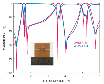
Figure 7 Simulated and measured results of the fabricated filter and its photograph.
Conclusion
In this article, a miniature tri-band BPF using a short-stub loaded SIR has been proposed. Based on the proposed SIR, a compact tri-band BPF with extended feed lines is implemented to achieve the miniaturization. Furthermore, four transmission zeros are produced and greatly improve the selectivity and stopband suppression. The measured result agrees with the electromagnetic (EM) simulation. For a system integrating GPS, WiMAX and WLAN, this concept could be applied to filter signals among these commercial bands.
Acknowledgments
This work was supported by the National Science Foundation of China (No. 61061001) and 555 Talent Program of Jiangxi Province of China.
References
- Y.S. Lin, C.C. Liu, K.M. Li and C.H. Chen, “Design of an LTCC Triple-band Transceiver Module for GPRS Mobile Applications,” IEEE Transactions on Microwave Theory and Techniques, Vol. 52, No. 12, December 2004, pp. 2718-2724.
- M. Makimoto and S. Yamashita, “Bandpass Filters Using Parallel Coupled Stripline Stepped Impedance Resonators,” IEEE Transactions on Microwave Theory and Techniques, Vol. 28, No. 12, December 1980, pp. 1413-1417.
-
H.L. Zhang and K.J. Chen, “A Tri-section Stepped-impedance Resonator for Cross-coupled Bandpass Filters,” IEEE Microwave and Wireless Components Letters, Vol. 15, No. 6, June 2005, pp. 401-403.
H.W. Liu, “Design of Triple-band Microstrip Bandpass Filter Using Folded Triple-section Stepped-impedance Resonator,” Microwave and Optical Technology Letters, Vol. 52, No. 4, April 2010, pp. 895-897. - C.H. Lee, C.I.G. Hsu and H.K. Jhuang, “Design of a New Triple-band Microstrip BPF Using Combined Quarter-wavelength SIRs,” IEEE Microwave and Wireless Components Letters, Vol. 16, No. 11, November 2006, pp. 594-596.
- Q.X. Chu and X.M. Lin, “Advanced Triple-band Bandpass Filter Using Triple-section SIR,” Electronics Letters, Vol. 44, No. 4, 2008, pp. 295-296.
- X.S. Zhang, B. Liu, Y.J. Zhao, J.K. Wang and W. Chen, “Compact and High Selectivity Dual-band Dual-mode Microstrip bpf with Five Transmission Zeros,” Microwave and Optical Technology Letters, Vol. 54, No. 1, January 2012, pp. 79-81.
- C.F. Chen, T.Y. Huang and R.B. Wu, “Design of Microstrip Bandpass Filters with Multiorder Spurious-mode Suppression,” IEEE Transactions on Microwave Theory and Techniques, Vol. 53, No. 12, December 2005, pp. 3788-3793.