
 The great diversity of commercially available annularly corrugated 7/8 inch feeder cables presents an increasing logistical challenge to users such as cable manufacturers, network operators and installation companies. Always selecting the right combination from the host of cables and connectors available and making sure that the selected combination is the best for the application is a major problem for customers and suppliers alike.
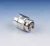
Consequently, the engineers at SPINNER set about tackling this difficult problem by developing a connector that is not only designed to ‘fit’ all 7/8 inch cables offered by the leading manufacturers, but will also meet the electrical and mechanical requirements of cables used in mobile communication systems.
The result is the MultiFit™ connector series, which, as the only connector currently on the market that ensures compatibility with all common 7/8 inch cables with annular corrugation, has advantages for both manufacturers and customers. For example, the reduction in the diversity of connector types has a positive effect on warehousing costs, while the connector is also attractive to users who were formerly bound to cables and connectors from one manufacturer.
Developing the MultiFit
Initially the questions that were addressed when developing the MultiFit connector series included: Which cables should be catered for? How could the connector adapt to the differences between those cables? And what should be the mechanical and electrical specifications? Table 1 answers the first question as it lists the cables that the MultiFit addresses.
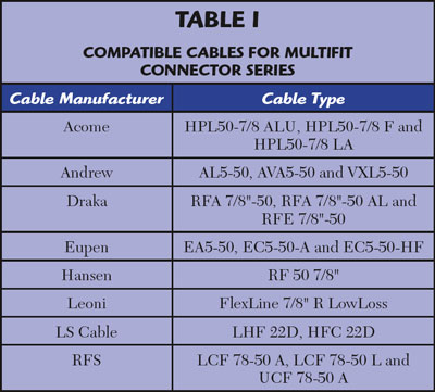
Table 1 Compatible Cables for MultiFit Connector Series
Secondly, the differences between some of these cables are quite significant, beginning with the materials that are used, such as aluminum and copper for the cable outer conductor. Also, the geometry, i.e. the shape of the outer conductor corrugation, varies quite significantly between manufacturers and between materials. The dimensions of nominal sizes and tolerances vary between manufacturers; some cables have a smooth inner conductor while others have a helically corrugated inner conductor. Figure 1 shows some of the variations.
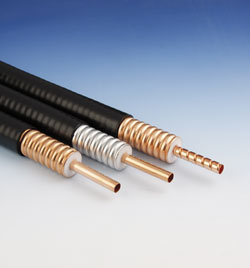
Figure 1 Examples of cables that can use MultiFit connectors.
In order to make the MultiFit connector ‘fit all’, certain design decisions were made. The first was that the cable should be prepared by one straight rectangular cut, resulting in a contact of the connector inner conductor on the inside of the tubular cable inner conductor. This means that the connector’s inner conductor contact element has to compensate for the differences in the nominal size and tolerance values of the inner conductors of the various cables in order to achieve even contact pressure.
Also, cables with a helically corrugated inner conductor present an additional challenge because their nominal size not only differs greatly from that of smooth inner conductors, but the helical corrugation means that the diameters within the inner conductor itself vary. However, the spring properties of the MultiFit connector’s specially designed inner conductor contact, in combination with the bending geometry and the dimensions of the support on which the contact element is fixed, make it possible to compensate for such diameter variations of up to 1.5 mm between the inner conductors. This is almost 20 percent of the inner conductor diameter. Also, the contact element is shaped so as to keep the insertion forces on all cables within a small range regardless of the large number of cable versions.
Maintaining Contact
In order to meet the exact demands regarding Passive Intermodulation (PIM), the contact force has to be sufficiently high enough and the contact clearly defined, which is why the contact element for the inner conductor used in the MultiFit connector has rounded contact faces. During insertion of the connector to the cable this shape prevents chipping, scratching or deformation, all of which could result in inadequate contact. Furthermore, this special contact design is able to compensate for cable eccentricities to a certain extent. All of these features mean that a high PIM-stability can be achieved under static and dynamic conditions.
The outer conductor contact between the connector and cable is established by clamping the cable’s outer conductor. This means that the size of the connector’s contact zone has to be matched with its material properties such as the tensile and compressive strength of the cable’s outer conductor. The clamping force must be lower than the yield strength of the material in order to prevent damage such as cracking or loose connections due to yielding material.
Therefore SPINNER selected an outer conductor clamping element similar to those used in the company’s well known Cut And Fit® connectors. Thus, when the connector is installed, the wave-shaped cable outer conductor is deformed into a cone shape and pressed against the contact surface of the connector. However, the radius of the cable’s outer conductor varies with the wave shape, resulting in varying lengths of the cone shape. The cable/connector interface therefore needs to be clearly defined as to have enough material available for a good mechanical and electrical contact for all cable types.
Seal of Approval
SPINNER holds the view that the seal between the cable and connector works best if the sealing element is placed on the outer conductor on the cable side, which means that the sealing element design must take the size and geometry of the outer conductor into account. The corrugation geometry plays an equally important role in the sealing element design.
For the MultiFit connector series, tightness in the transverse direction is generated between the cable’s outer conductor and the connector’s housing. Because of the different dimensions and shapes of the cable outer conductors, an intelligent sealing element has been designed. The sealing element has to provide enough pressure to provide perfect sealing for any cable type while not producing a surface pressure that is so high that it would require an increased mounting force. Not forgetting that the sealing element also has to compensate for any possible shape irregularity caused by the welding seam.
Accessories
It is equally important to bear the various cable designs in mind when accessories and mounting tools are developed, whether it is a cable cutting and stripping tool or the saw jig supplied with the connector, which guides a handheld saw. These tools must also fulfill their function with every cable type. On the one hand the cables must not be damaged, while on the other hand the saw jig and cutting and stripping tool must be placed on the cable with as little play as possible. This is necessary in order to ensure an even cable cut because the cable face directly influences the RF space in the connector and thus the connector’s VSWR.
When SPINNER developed the RF path for the MultiFit connector series it became clear that even small differences in the cables from various manufacturers result in a reasonable decrease in the electrical performance. In particular, cables with a helically corrugated inner conductor showed this behavior. Nevertheless, the engineers managed to find a geometry for the connector’s RF path that can compensate for all of these cable-related factors and keep the connector reflection to an extremely low level with all cable types. VSWR values for the MultiFit connector series are shown in Figure 2.
Figure 2 Typical VSWR for the MultiFit connector series.
SPINNER has developed a connector that is not only unique in fitting most common annularly corrugated 7/8 inch cables, but which also meets the demanding requirements regarding Passive Intermodulation (PIM) and VSWR (Figure 3 shows a typical static PIM for the MultiFit connector series and Figure 4 shows a typical dynamic PIM). The typical VSWR values for the connector series (for connector interface 7-16) are 1.02 up to 1 GHz, 1.03 from greater than 1 up to 2.7 GHz and 1.06 from greater than 2.7 up to 3.8 GHz.
Figure 3 Typical static PIM for MultiFit.
Figure 4 Typical dynamic PIM for MultiFit.
The connectors also meet the requirements of the relevant standards for electric strength, insulation resistance, etc. For Passive Intermodulation, which is measured according to IEC 62037, Appendix A1, the system reliably meets the highest demands for static and dynamic measurements for all cable types. And while weighing only 150 g and measuring less than 50 mm, the connector features high mechanical stability and meets IP68 requirements.
In its design, important consideration was given to the connector’s corrosion resistance as both materials used for cable outer conductors, aluminum and copper, generate different electrochemical potentials in connection with the surface coating of the connector parts. The resulting solution has proved itself by withstanding extensive tests in the salt spray chamber.
Conclusion
By taking advantage of SPINNER’s 60 years of experience in the RF field, the company has produced the MultiFit connector series that offers the user a high degree of flexibility, excellent quality and easy handling all in one compact, lightweight housing.
SPINNER GmbH,
Munich, Germany,
+49 89 12601-0,
info@spinner.de, www.spinner.de.
RS No. 303