
For decades, the microwave and optical domains lacked a practical phase-coherent link, with advances in each domain proceeding largely independently.1 Recently, commercial ultrastable microwave systems (UMS) have begun to transform this paradigm by providing robust, phase-coherent connections between the two domains in turnkey devices — capabilities previously confined to complex experimental apparatuses in specialized laboratories. By employing optical frequency division (OFD), UMS transfer the exceptional frequency stability of state-of-the-art optical oscillators to the microwave domain, enabling ultra-low noise signals for next-generation timing and communication systems.
CONVENTIONAL RF VERSUS OPTICAL OSCILLATORS
Any microwave precision application is closely tied to the development of ever “better” microwave sources, where “better” typically refers to reduced fluctuations in the output frequency. Yet such frequency fluctuations, arising from continuous frequency drifts or sudden phase jumps, are inherent to any real-world frequency generator. They are commonly expressed as frequency (phase) stability in the time domain, and as spectral purity in the frequency domain. Maximizing these metrics can be challenging, as it often requires substantial increases in cost and system complexity for even modest improvements. This challenge arises in part from fundamental physical limits. If microwave signal generation relies on the up-multiplication of RF signals — as delivered, for example, by the ubiquitous oven-controlled crystal oscillators (OCXOs) — any frequency up-conversion inevitably multiplies the phase noise as well. Atomic frequency standards (such as rubidium or cesium commercial clocks) and masers are still the standards for obtaining the most stable signals in the long-term, but often rely upon synthesis based on OCXOs as local oscillators (LO), limiting the short-term frequency stability and spectral purity. OCXOs are fundamentally limited by the intrinsic properties of quartz crystal resonators, with the best devices achieving fractional frequency stabilities around mid-10-14 at integration times of 1 second.

Figure 1 Optical frequency division (OFD) divides down the electromagnetic field of an external optical reference to an ultrapure microwave signal.
In fact, the most stable human-engineered oscillators to date operate at optical carrier frequencies, based on continuous-wave optical lasers stabilized to high-Q factor optical Fabry-Perot resonators. For example, for optical signals at 194.4 THz (corresponding to the common laser wavelength 1.54 μm), fractional frequency instabilities as low as 3×10-17 over a 1 sec averaging time have been demonstrated, far surpassing the performance of any electronic RF oscillator. Intuitively, this suggests synthesizing microwave signals by frequency division of optical carriers rather than by up-multiplication of RF signals, thereby leveraging the reduction rather than amplification of phase noise (see Figure 1). Early efforts to implement this concept of OFD and to bridge the optical and RF domains date back to the 1960s — at that time, however, relying on radio-optical systems of overwhelming complexity. Achieving a practical link capable of coherently uniting the electromagnetic spectrum required decades of further research, ultimately culminating in a Nobel Prize-winning idea: the optical frequency comb.2,3
OPTICAL FREQUENCY COMBS
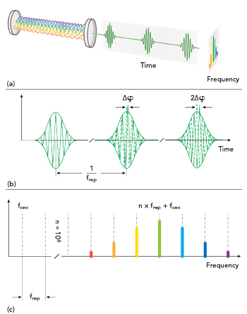
Figure 2 Optical frequency comb produced by a mode-locked laser (a); In time domain, the pulses are separated by the inverse of the repetition rate (frep). Note that in the general case, the carrier-envelope phase undergoes a slip from pulse to pulse (b); In frequency domain, the comb is offset by a certain amount fceo, but otherwise entirely composed of equally spaced frequencies that are separated by the repetition rate frep (c).
Simply put, an optical frequency comb is a special type of laser that produces a spectrum of equally spaced light frequencies, resembling the teeth of a comb in frequency domain — hence the name. Frequency combs are typically produced using mode-locked lasers (see Figure 2a). Mode-locking is a form of (trigged) self-organization among the phases of the laser cavity modes, enabling the formation of a regular ultra-short pulse train, ensuring equal frequency spacing and phase synchronization between individual modes. This pulse circulates within the laser resonator at a specific repetition rate (frep), typically within the range of tens of MHz to a few GHz. The laser output, a train of ultra-short pulses, is generated by transmitting copies of this circulating pulse through a partially transparent end-mirror of the cavity. It is important to note that due to dispersion within the laser cavity, group velocity differs from phase velocity. As a result, from pulse to pulse, the carrier-envelope phase undergoes a slip, meaning the envelope shifts relative to its carrier wave (see Figure 2b).
In the ideal case — i.e., in the absence of external perturbations — the Fourier relationship between time and frequency domains dictates that a periodic pulse train in time corresponds to a series of discrete frequency modes. In frequency domain, the frequencies of the comb are given by:
fopt, n = n frep + fceo
where fopt, n is the optical frequency of the n-th comb line, n is an integer index, frep is the repetition rate of the laser and fceo is the carrier-envelope offset frequency. In other words, the frequency comb is offset by a certain amount, fceo (a consequence of the pulse-to-pulse carrier-envelope phase slip), but otherwise entirely composed of equally spaced frequencies that are separated by the repetition rate frep (see Figure 2c). The above equation represents a landmark achievement, as it decomposes an optical-domain frequency (fopt, n) into two frequencies that lie in the RF domain (frep and fceo). As a result, optical frequency combs provide a unique link between optical frequencies (in the hundreds of terahertz) and radio frequencies, thereby bridging a frequency gap of up to six orders of magnitude.
OPTICAL FREQUENCY DIVISION
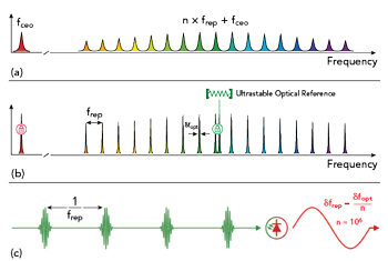
Figure 3 Optical frequency division (OFD): Free-running frequency comb, operated without any active stabilization loops (a); By locking the frequency comb spectrum at two points, the spectral purity of an external optical reference is precisely replicated across all optical comb lines (b); In time domain, the periodic pulse train undergoes a dramatic reduction in timing jitter. When such a pulse train impinges on a suitable photoreceiver, it generates an RF signal at the repetition rate frequency (frep) with ultra-low phase noise (c).
In a manner akin to a reduction gear, optical frequency combs can be used to divide optical frequencies down to the RF domain. While such OFD is conceptually simple, its practical implementation comes with challenges. As schematically illustrated in Figure 3a, free-running frequency combs, operated without any active stabilization loops, exhibit linewidths far from those required for high-precision applications. Instead, both degrees of freedom — the carrier-envelope offset frequency and the repetition rate — need to be measured and actively stabilized, which implies the need for introducing suitable actuators that allow appropriate control of both.
As to the carrier-envelope offset frequency, notably, measuring and stabilizing fceo (also known as self-referencing) posed significant challenges in the early development of optical frequency combs. One of the early strategies has been to employ optical frequency conversion schemes that aim to circumvent the explicit measurement and control of fceo altogether. The advent of octave-spanning frequency combs, those covering an optical frequency range of more than twice the lowest optical frequency, has enabled a simple yet efficient implementation widely known in the community as the “f-2f” method.
With the lowest-frequency comb tooth (fceo) pinned, the second degree of freedom can be addressed through a so-called “optical lock” of one of the optical comb teeth (fopt, n) to an external optical reference frequency (Figure 3b). An optical lock operates by continuously measuring fopt, n against the optical reference to detect any drift and applying a feedback loop to keep the comb tooth precisely aligned. As illustrated in Figure 3b, having anchored the frequency comb spectrum at two points, the spectral purity of the external optical reference is not only transferred to the adjacent comb tooth but is also precisely replicated across all optical comb lines. This so-called spectral purity transfer is fundamental to the realization of OFD, as it dramatically stabilizes the line spacing (frep) of all comb teeth. Intuitively, this happens because fluctuations are divided over the entire frequency spacing between the two pinning points.
Switching to the time domain (see Figure 3c), the laser-generated periodic pulse train exhibits a dramatic reduction in timing jitter. When such a pulse train impinges on a suitable photoreceiver, it generates an RF signal at the repetition rate (frep) with ultra-low phase noise, thereby accomplishing OFD.
In a simplified picture, the principle of OFD can be conveyed by considering fluctuations in the comb equation:
δfopt, n = n δfrep + δfceo
and rearranging the above equation to
δfrep = (δfopt, n - δfceo) / n.
When δfceo is well-controlled, it can be brought to zero, and the above relation simplifies to
δfrep ≈ δfopt, n / n,
i.e. the fluctuations of the optical comb tooth (δfopt, n) are divided down by the mode number n.
In other words, the frequency line spacing (frep) will inherit the frequency stability of the external optical reference. It should be emphasized that the associated phase noise will scale with the power of n2, with n being on the order of 105 - 106, so that the resulting phase noise can be potentially (in the theoretical limit) reduced quadratically with respect to the carrier signals’ frequency ratio. For example, assuming an ultrastable optical frequency reference operating at 1550 nm (approximately 194 THz), and its OFD into a 10 GHz microwave carrier, the potential phase noise reduction factor amounts to the impressive value of -86 dB. In this context, it is essential to note that non-self-referenced frequency combs — such as microresonator (Kerr) combs and other microcombs without measured and stabilized carrier-envelope offset — offer only partial phase coherence for OFD, thus yielding much lower phase noise reduction factors. Recent leaps in integrated photonics are showing rapid advances: seminal academic works are already demonstrating impressive short-term spectral purity.4
In summary, OFD locks the electromagnetic field of an external optical reference to a single tooth of an optical frequency comb, enabling the comb to divide it down to an ultra-pure RF signal, which is then extracted using suitable opto-electronics. Accordingly, an OFD system consists of three main sub-units: (1) An ultrastable optical reference, acting as a flywheel, (2) an optical frequency comb, functioning as a reduction gear and (3) an RF extraction unit, tailored to the desired RF output frequency. Each of these components involves intricate details that are, in themselves, a refined art of science and technology. It is no surprise that commercially available, integrated UMS required years of dedicated research, development and integration engineering.
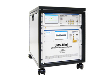
Figure 4 Integrated ultrastable microwave systems can be compactly housed in rack-mounted, portable devices, making ultra-stable microwave systems accessible to a wide range of end-users.
In 2016, a world record for the lowest phase noise on an X-Band microwave signal was demonstrated using a laboratory setup5 — notably a record that still stands at the time of this article. Building on this success, a fully integrated, transportable prototype was introduced three years later.6 Today, such systems can be constructed in rack-mounted, portable devices, making UMS accessible to a wide range of end-users (see Figure 4).
SETTING NEW STANDARDS IN RF PHASE NOISE ANALYSIS
Until a decade ago, microwave sources based on OFD were largely confined to complex laboratory experiments. In recent years, substantial momentum has been gained toward making such systems more robust and rugged, not least to enable in-field operation. Readily delivering fractional frequency stabilities at the 10-15 level on second timescales, UMS nowadays are a new class of commercially available microwave oscillators, offering phase noise levels once thought unattainable.
These developments underscore the importance of accurately estimating and measuring the figures of merit for this class of oscillators, such as phase and amplitude noise present in the sources as phase and amplitude modulation of the signal carrier. Phase noise metrology offers several approaches for measuring phase noise, with the appropriate methodology depending on the characteristics and stability class of the device under test (DUT). For characterizing DUTs with very low levels of phase noise, modern high-end phase noise analyzers employ specialized hardware and, most importantly, cross-correlation, a well-established method for suppressing the contribution of instrument phase noise. By splitting the DUT signal into two paths and referencing each of the two paths to an independent LO, their subsequent cross-correlation suppresses (uncorrelated) instrument noise and reveals the (correlated) DUT’s phase noise. Yet, standard-configured commercial instruments, even when based on the best available OCXOs with fractional frequency stabilities in the low 10-13 to high 10-14 range, are unable to support consistent measurements at the purity levels achieved by UMS operating in the 10-15 level.
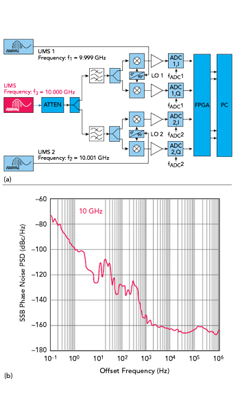
Figure 5 Setup for characterization of an ultralow-noise microwave oscillator using a commercial best-in-class phase noise analyzer (a); phase noise measurement of the UMS at 10 GHz using two additional UMS systems slightly above/below 10 GHz as external local oscillators (b).7
The challenge sparked a collaboration between Rohde & Schwarz and Menlo Systems, with the goal of demonstrating a handy measurement setup capable of revealing the phase noise performance of the world’s purest microwave signals. The approach was to pair a best-in-class phase noise analyzer with two UMS as LOs and benchmark the setup using a third UMS as the DUT (see Figure 5a). The result was a turnkey measurement setup with record-breaking sensitivity.7 For the first time, an ultra-low noise microwave oscillator has been characterized using a turnkey commercial phase noise analyzer — at noise levels previously buried in the instrument’s noise floor. For a 10 GHz carrier, with only a few cross-correlations, the team demonstrated phase noise as low as < -90 dBc/Hz at 1 Hz offset and < -150 dBc/Hz at 1 kHz offset, and a fractional frequency stability of < 4 × 10-15 at 1 sec (see Figure 5b). This configuration is around 30 dB more sensitive close to carrier than any commercial phase noise analyzer operating in standard mode.
On the one hand, the measurements confirm that the residual phase noise of the UMS lie well below the analyzer’s noise floor, unambiguously qualifying them as the reference oscillators of choice for future ultra-sensitive phase noise measurements. On the other hand, greatly enhanced sensitivity enables resolution of extremely low-level noise components, supporting UMS engineering studies of fundamental noise processes that were previously inaccessible due to prohibitively long measurement times. Accurate pilot studies on phase noise metrology at these levels of spectral purity are now underway, given the importance of understanding the validity and associated uncertainties of these measurements. Overall, these findings exemplify cross-disciplinary synergy and are expected to expand the horizons of applications such as advanced RF communication, timing and radar.
OUTLOOK
OFD of high-fidelity optical references generates microwave signals with unprecedentedly low phase noise levels. It is now possible not only to generate, but also to fully characterize such ultrastable microwaves in a truly turnkey fashion. Delivering stability improvements ranging from a single order of magnitude in commercial systems to two or three orders of magnitude in laboratory demonstrations, OFD is undoubtedly positioned to ultimately surpass OCXOs in many high performance applications. While these advances are only beginning to reach communities seeking the highest-fidelity RF and microwave signals — some of which have had little interaction with the photonics world until now — they represent a significant opportunity for cross-disciplinary enrichment.
References
- S. A Diddams, K. Vahala and T. Udem, "Optical frequency combs: Coherently uniting the electromagnetic spectrum," Science, 369, 6501, 2020, 10.1126/science.aay3676.
- T. W. Hänsch, "Nobel lecture: Passion for precision," Reviews of Modern Physics 78, 1297, 2006, Web: https://doi.org/10.1103/RevModPhys.78.1297.
- J. L. Hall, "Nobel lecture: Defining and measuring optical frequencies," Reviews of Modern Physics, 78, 4, 1279, 2006, 10.1103/RevModPhys.78.1279.
- I. Kudelin et al., "Photonic chip-based low-noise microwave oscillator," Nature, 627, 534, 2024, 10.1038/s41586-024-07058-z.
- X. Xie et al., "Photonic microwave signals with zeptosecond-level absolute timing noise," Nature Photonics, 11, 44–47, 2016, Web: https://doi.org/10.1038/nphoton.2016.215.
- M. Giunta et al., "Compact and ultrastable photonic microwave oscillator," Optics Letters, Vol. 45, p. 1140, 2020, Web: https://doi.org/10.1364/OL.385503.
- M. Giunta et al., "Cross-Spectrum Phase Noise Measurements of Ultrastable Photonic Microwave Oscillators," IEEE Transactions on Microwave Theory and Techniques, 74, 348-355, 2026, 10.1109/TMTT.2025.3610271.