
Phase noise is the most important figure of merit of microwave oscillators.1,2 Although a number of publications have addressed this phenomenon, it still remains one of the most challenging aspects in oscillator design. This article briefly summarizes the research and development effort in the area of low-noise signal generation. It discusses a general noise generation mechanism, the influence of individual elements on phase noise behavior as well as various noise-reduction techniques.
Phase Noise Phenomenon and Modeling
A typical feedback microwave oscillator, shown in Figure 1, consists of a passive frequency-determining resonant element and an active device required to compensate for the resonator losses in order to start oscillations. The oscillations are initiated due to small, noisy signal fluctuations occurring in the oscillator components. The active device small-signal gain has to be greater than the resonator loss resulting in a rapid increase of the active device output signal. Obviously, some kind of limiting mechanism (such as gain compression) is required to stabilize the output power at a certain level. The gain compression usually occurs in the active device itself due to its natural nonlinear behavior. Thus, at steady state the active device gain becomes equal to the overall loss in the resonator-feedback path that stabilizes the output signal amplitude. The oscillation frequency is determined by the resonator frequency selectivity and phase relationship in the oscillator-feedback path.
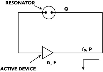
Figure 1 Conceptual block diagram of an oscillator.
Thus, it is important to understand that two essential requirements are necessary to realize an oscillator:
- noisy signal fluctuations in oscillator components are required to initiate oscillations
- a limiting, nonlinear mechanism is required to achieve steady-state oscillations
Unfortunately, these vital features of the microwave oscillator eventually result in output spectrum contamination either directly (that is due to the active device RF noise or resonant-frequency fluctuations) or indirectly (that is due to the up-conversion of the active device low-frequency noise in its nonlinearities). The oscillator noise behavior has been extensively investigated3-6 and can be represented as follows:

where:
G = active device gain
F= active device noise factor
k = Boltzman’s constant
T = absolute temperature
P = RF power applied to the resonator
Q = resonator loaded Q-factor
ƒ0 = oscillation frequency
ƒα = active device flicker-corner frequency
ƒ = offset frequency
This expression is a well-known modification of Leeson’s equation that depicts the oscillator phase-noise behavior in the offset frequency domain. Although the formula defines four basic frequency offset regions, in microwave oscillators the 1/ƒ term is usually ignored due to the 1/ƒ2 noise domination that leads to the “classical” oscillator phase-noise profile shown in Figure 2. For offset frequencies higher than the resonator half bandwidth ƒ0/2Q, the phase noise is mainly determined by the available RF power level and the active device thermal noise. This region shows a nearly flat response called “noise floor.” For frequencies between the half bandwidth and flicker-corner frequency ƒα, the phase noise increases at a 20 dB per decade rate. In the last region, where the flicker noise dominates, the phase noise increases at 30 dB per decade. Thus, two important oscillator parameters, namely the resonator half bandwidth ƒ0/2Q and flicker corner frequency ƒa, define the shape of the phase-noise curve, while its magnitude is mainly determined by the  term.
term.

Figure 2 Phase noise behavior of a microwave oscillator.
This graph gives a simplified yet very helpful visualization of the phase-noise behavior as well as some intuitive ideas on how to reduce its appearance in the oscillator output spectrum. The phase noise can be controlled by reducing the flicker-corner frequency ƒα and/or the resonator half bandwidth ƒ0/2Q as shown. The flicker-corner frequency is mainly determined by a particular active device and its operating regime, while the half bandwidth is set by the frequency resonator and its coupling scheme. Clearly, utilizing low-flicker-noise devices (such as silicon-bipolar transistors) and applying a high-Q frequency resonator technology are effective and commonly used ways to clean up the oscillator output spectrum.
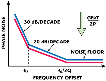
Figure 3 Another method for phase noise reduction.
Alternatively, the entire noise curve can be shifted down, as shown in Figure 3, by increasing the oscillator signal-to-thermal noise ratio. This can be practically achieved by maintaining a higher power level in front of the resonator and/or reducing the active device noise factor, while the active device gain should be set to its optimum value (determined by the resonator coupling as will be discussed below). Thus, extracting a higher power from the active device can provide a considerable effect: the entire phase-noise curve is shifted down, dB for dB. However, the output power increase should be implemented very carefully, since a severe phase-noise degradation can occur because of the active device noise elevation at compression. Thus, the active device should be preferably operated in a small-signal, “linear” regime in order to keep its noise characteristics unaffected. This may sound confusing since in order to get steady-state oscillations, a limiting mechanism is required—that is something has to be nonlinear. However, “something” does not necessarily mean the active device itself. The limiting mechanism can be effectively spread through oscillator components or even moved from the active device to a less critical (from the noise generation point of view) component. In a more general sense, the main idea here is to reduce the influence of oscillator nonlinearities on the phase noise generation process that can be achieved with a variety of linearization and noise suppression techniques.
In summary, the key principles in designing low-noise microwave oscillators are as follows:
- reducing the oscillator half bandwidth frequency by utilizing a high-Q resonator and optimum coupling scheme.
- reducing the flicker-corner frequency by choosing an appropriate active device and its operating regime.
- increasing the oscillator signal-to-thermal noise ratio by choosing an active device with a low noise figure and maintaining high signal level in front of the resonator.
- preventing the active device noise elevation by optimizing the oscillation-limiting mechanism as well as applying active device linearization and noise-reduction techniques.
Frequency Resonators
The frequency resonator element has the most considerable impact on oscillator phase-noise and tuning characteristics. Modern microwave oscillators utilize various resonator technologies, based on electromagnetic, electro-acoustic and electro-optical principles.
Electromagnetic Fixed-frequency Resonators
An air-filled metal cavity is a typical example of a high-Q electromagnetic resonator, which confines the electromagnetic energy inside a shielded volume.7 The cavity is usually a cylinder made from a temperature-stable material such as Invar, while its internal walls are plated and thoroughly polished to minimize the surface resistivity. Since dielectric dissipation and radiation loss are eliminated, the achievable Q is mainly limited by the loss in the metal walls and can be fairly high (10,000-70,000). In spite of the high achievable Q-factors and excellent power handling capabilities, the impractically large size of cavity resonators restricts their application in signal generation.
Smaller sizes are realizable using dielectric resonators. The practical frequency range for the dielectric resonators is between 1 and 40 GHz, while their Q-factor typically reduces linearly with increasing frequency. A Q of 10,000 at 4 GHz is an average representative of commonly used materials.8-10
Ceramic resonator oscillators (CRO) offer a low-cost solution for frequencies between a few hundred MHz and a few GHz. The resonator is a silver-plated length of temperature-stable ceramic, shorted on one end; achievable Q-factors are comparable to the dielectric resonator pucks. Their low cost and easy implementation make them an excellent candidate for low-cost CRO modules, which are commercially available up to 8 GHz.11
Much higher Q-factors are achievable using sapphire resonators. The resonator is a cylinder made from a single crystal Al2O3 material known as sapphire. The material features extremely low dielectric loss at microwave frequencies. The typical Q-factor of a sapphire resonator used in the fundamental TE01d mode is 40,000-50,000. The higher-order, so-called “whispering-gallery” modes are utilized to isolate the electromagnetic energy inside the resonator, and therefore reduce the influence of the external elements. Q-factors greater than 200,000 at room temperature have been reported.12-16
Electromagnetic Tunable Resonators
The main disadvantage of the resonators described above is their limited tuning range, since any resonator detuning adversely affects its Q characteristics. Even frequency locking can be a certain challenge for high-Q resonators such as sapphire. Yttrium iron garnet (YIG) resonators are utilized when wideband tuning and high Q-factors are simultaneously required. The YIG resonator consists of a small (8-20 mils in diameter) sphere placed between the two poles of a cylindrically re-entrant electromagnet and coupled with small wire loops. Frequency tuning is possible since the resonant frequency of the spherical YIG resonator is in direct proportion to the applied magnetic field.17-23 Thus, the resonant frequency and, consequently, the oscillating frequency can be controlled by changing the DC current injected into the electromagnet tuning coil. YIG resonators offer a relatively high Q (greater than 4,000 at 10 GHz), which linearly increases with frequency. A practical usable frequency range of pure YIG resonators lies between 2 and 50 GHz, similar to the frequency range of dielectric resonators. Lower operating frequencies (a few hundred MHz) are obtainable by adding special dopants (such as gadolinium), although that degrades the Q-characteristics. The highest boundary is mainly limited by magnet saturation and impractically high power consumption, due to the very high current required to generate the necessary magnetic field strength.
Smaller size and lower-cost characteristics are achievable with varactor-tuned oscillators (usually referred to as voltage-controlled oscillators or VCOs), based on either lumped LC or distributed microstrip resonators.24,25 Frequency tuning is achieved using varactor diodes, since their capacitance depends on the applied tuning voltage. Unfortunately, the Q-factors of these resonators are not high; typical values are between a few tens to a few hundreds, depending on a particular technology and tuning range. Thus, the VCO free-running noise is significantly higher in comparison with YIG-oscillator numbers. Nevertheless, the VCO is an attractive choice in designing a multi-loop PLL synthesizer, since its noise can be suppressed by utilizing a low-noise, fixed-frequency reference oscillator (such as an OCXO) as well as a very wide loop bandwidth. Using a high-quality, single-frequency reference oscillator and a low residual noise, wideband (up to a few MHz) locking mechanism, the VCO-based synthesizers can potentially achieve sec-fast tuning, together with YIG-like noise performance, without the use of expensive, bulky and power-hungry YIG devices.26
Electro-acoustic Resonators

Figure 4 Electro-acoustic resonator concept.
A generic electro-acoustic device combines electrical-to-acoustic and backward acoustic-to-electrical signal transducers with a high-Q acoustic resonator, as shown in Figure 4. A “classical” representative is the crystal resonator, which has demonstrated exceptional high-Q and stability characteristics and has been widely used in low-noise oscillators from low RF through a few hundred MHz. At higher frequencies, surface acoustic wave (SAW) resonators are the most commonly used devices. The SAW resonator structure is deposited onto a low-acoustic-loss substrate (such as lithium niobate) and exhibits high-Q characteristics at RF and microwave frequencies up to 2 GHz.27,28 The film bulk acoustic resonator (FBAR) is another representative of the electro-acoustic resonator family. The resonator is a three-layer structure with the top and bottom electrodes of molybdenum sandwiching a middle layer of aluminum nitride.29 FBARs can be used in the frequency range of a few hundred MHz to approximately 5 GHz, with a typical Q-factor of greater than 500 at 2 GHz.
Electro-optical resonators
Electro-optical principles are utilized in an elegant optoelectronic oscillator (OEO), which is capable of generating a signal at microwave frequencies.30 The OEO generic architecture is essentially a transposed gain oscillator that utilizes laser light energy to enable an electro-optical signal conversion. The laser radiation propagates through a modulator and an optical energy storage element (that is a resonator) and then is converted to electrical energy with a photo-detector, as depicted in Figure 5. The electrical signal at the output of the photo detector is amplified, filtered and fed back to the modulator to close the oscillator feedback loop.
The optical resonator is usually constructed using a long fiber delay line; the Q-factor is proportional to the ratio of the delay time and line loss. Since fiber lines exhibit fairly low insertion loss (less than a dB per km), high-Q resonators can be constructed. A loaded Q-factor of 10,000 has been reported using a 2 km fiber line;31 the longer fibers exhibit even higher Q-factors. Further improvements are possible with a microspherical optical resonator that utilizes multiple reflections inside a fused-silica sphere.32
Coupling
Resonator coupling is another important consideration because any coupling mechanism reduces the residual (unloaded) resonator Q-factor to the actual (loaded) value used in phase-noise calculations. It is a common design mistake to achieve high loaded Q values by using a very loosely coupled resonator. Resonator loss is a function of its unloaded and loaded Q-factors and is given by:

where QU and QL are the resonator unloaded and loaded Q-factors, respectively.
The undercoupling results in increased overall resonator loss requiring an extra amount of gain to compensate it, which in turn, results in thermal noise increase. Since these two factors work in opposite ways, intuitively, there should be a certain optimum determined by a specific oscillator topology. For example, for the simple feedback oscillator shown previously, the phase-noise minimum is achieved when the resonator loaded Q-factor is set to one half of its unloaded value (QL = 0.5 QU) that corresponds to a 6 dB resonator loss.33,34 Other oscillator schemes may require different optimum coupling values due to different design goals and tradeoffs. For example, near optimum results with QL = 0.375 QU coupling have been achieved for a more complex frequency-locked oscillator design.35

Figure 6 Single port arrangement.
Moreover, the coupling structure does not necessarily have to be symmetrical, that is the two resonator ports may have different coupling coefficients, as required by a particular oscillator scheme.35,36 For example, a circulator-based oscillator, shown conceptually in Figure 6, utilizes a feedback signal reflected from one resonator port only, while the second port is used to extract the output frequency. The output frequency can be also extracted from the amplifier output (or input), thus eliminating the need for a second resonator port at all. No circulator is required in negative resistance designs, which utilize single-port resonators and are commonly used for wideband tunable oscillators.
Active Devices
Although oscillators can be constructed using various devices (such as Gunn or IMPATT diodes), bipolar and field-effect transistors are the most commonly used devices.10 The transistor gain, maximum oscillation frequency, output power and noise characteristics are the main parameters affecting oscillator design. These parameters are heavily dependent on a particular device; the most common technologies are silicon (Si), gallium arsenide (GaAs) and silicon germanium (SiGe).
Silicon-bipolar-junction transistors have dominated the oscillator field up to approximately 20 GHz due to their excellent 1/ƒ noise characteristics. GaAs FET and HEMT devices on the other hand have been demonstrated to oscillate at frequencies beyond 100 GHz as fundamental oscillators. Unfortunately, their flicker-corner frequency is also higher, compared to the silicon-bipolar transistors, which restricts their application in low-noise oscillator designs. In practice, it is more common to achieve millimeter-wave frequencies by using a lower-frequency silicon-bipolar transistor oscillator, followed by a frequency multiplier and bandpass filter. This arrangement usually results in better phase-noise performance, compared to fundamental, GaAs-based oscillators. SiGe is another very promising technology that combines excellent noise characteristics with high oscillation frequencies.
Noise-Reduction Techniques

Figure 7 Various realizations of limiting mechanisms.
Active device linearization is one of the techniques that help in preventing noise elevation. The simplest solution is to avoid or, more exactly, reduce active device compression by implementing another, less noisy limiting mechanism. Various techniques (or their combination) can be used, as shown in Figure 7.
A signal limiter can be placed either before or after the active device, keeping its output well below the compression level. For example, a close-in phase-noise reduction of 15 dB has been observed by adding a diode limiter in an X-band DRO design.37 The same function can be achieved with an automatic-level-control (ALC) feedback circuit that detects the active device output and adjusts the overall loop gain with an RF attenuator.27

Figure 8 RF feedback concept.
The RF signal sampled from the amplifier output can be fed back to, and subtracted from, the RF input signal directly without DC detection, as depicted in Figure 8. This is essentially a generic feedback concept, which can be implemented in a variety of forms ranging from transistor-level local feedback circuits38,39 to more complex system-level solutions.40

Figure 9 Feed-forward concept.
Active device characteristics can also be linearized using a feed-forward amplifier approach.41 The feed-forward amplifier employs two cancellation circuits to generate an error signal and then subtract it from the main amplifier output, as shown in Figure 9. By properly balancing amplitude and phase characteristics, it is possible to remove undesired artifact products created by the main amplifier. This approach is widely used to suppress amplifier intermodulation distortion products; however, it can be effectively utilized for noise reduction as well.34,40 The level of suppression is mainly limited by amplitude and phase balance; typical values are in the 15 to 40 dB range and can be further improved by applying a more sophisticated balance adjustment.

Figure 10 Transposed gain oscillator.
Another interesting method (shown conceptually in Figure 10) is based on the use of a transposed-gain amplifier.34,42 This scheme requires a lower frequency active device (compared to the oscillator output frequency) that is achieved by converting the signal in the frequency mixers. Thus, low-flicker-noise silicon-bipolar transistors can be utilized to generate output frequencies greater than their own maximum oscillation frequency. The auxiliary LO noise can be suppressed (to a certain degree, of course) by adjusting the phase delay between the mixer LO ports.
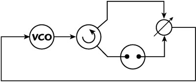
Figure 11 Frequency-locked oscillator.
Frequency-locking is another powerful approach in constructing low-noise oscillators.43,46 This approach utilizes a phase detector (usually a balanced mixer) to compare the two signals coming from a VCO directly and through a high-Q resonator used as an external frequency discriminator (see Figure 11). These two signals are adjusted to be in quadrature to increase the phase detector sensitivity. The phase detector produces a voltage that steers the oscillator to suppress its phase-noise fluctuations. The noise suppression is limited by the discriminator sensitivity, which in turn heavily depends on the resonator Q-factor.

Figure 12 Frequency-locked oscillator with a built-in discriminator.
Thus, a VCO phase noise can be drastically reduced by utilizing a high-Q external resonator, such as a metal cavity or sapphire. However, this circuit exhibits an initial frequency-lock acquisition problem due to the high-Q resonator characteristics. The problem can be elegantly solved by utilizing a common high-Q resonator, which is simultaneously used as both an oscillator resonant element and frequency discriminator (see Figure 12). A phase noise of -140 dBc/Hz at a 100 kHz offset from a 10 GHz carrier has been achieved using a conventional dielectric resonator with a loaded Q of 1,500 and an FET-based transistor amplifier.46
The discriminator sensitivity and consequently the phase-noise performance can be further improved by putting an additional low-noise amplifier (LNA) in front of the phase detector. However, the incident power coming to the LNA should be kept very low to minimize its flicker noise contribution. This can be practically achieved by utilizing a near-critical coupling resonator configuration47 or an interferometric signal processing.48,49 A phase noise of -150 dBc/Hz at 1 kHz offset and 9 GHz output has been achieved using a whispering-gallery-mode sapphire resonator and advanced interferometer-based noise suppression circuit.49
Conclusion
Phase noise remains the most critical specification and design challenge for microwave oscillators. Utilizing low-flicker-noise active devices and high-Q resonators are the most commonly used ways to achieve good phase-noise characteristics. Further improvements are brought on by increasing the output power extracted from the active device and simultaneously optimizing its nonlinear behavior with a variety of linearization and noise-reduction techniques. This article has briefly summarized the main methods; further details can be found in the following reference list. Many of the techniques discussed herein are currently implemented at a subsystem-level, using additional parts external to the oscillator itself. Combining and eventually integrating these solutions on a single chip will support the on-going demand for low-cost, high-performance microwave oscillators.
References
1. I. Bahl and P. Bhartia, Microwave Solid State Circuit Design, Second Edition, John Wiley & Sons Inc., Hoboken, NJ, 2003.
2. U. Rohde, A. Poddar and G. Bock, The Design of Modern Microwave Oscillators for Wireless Applications: Theory and Optimization, John Wiley & Sons Inc., Hoboken, NJ, 2005.
3. D. Leeson, “A Simple Model of Feedback Oscillator Noise Spectrum,” IEEE Proceedings, Vol. 54, No. 2, February 1966, pp. 329-332.
4. B. Parzen, “Clarification and a Generalized Restatement of Leeson’s Oscillator Noise Model,” 1998 IEEE International Frequency Control Symposium Proceedings, pp. 348-351.
5. J. Nallatamby, M. Prigent, M. Camiade and J. Obregon, “Extension of the Leeson Formula to Phase Noise Calculation in Transistor Oscillators with Complex Tanks,” IEEE Transactions on Microwave Theory and Techniques, Vol. 51, No. 3, March 2003, pp. 690-696.
6. E. Rubiola, “The Leeson Effect: Phase Noise in Feedback Oscillators,” 2006 IEEE International Frequency Control Symposium Tutorial, June 2006.
7. A. Sen Gupta, D. Howe, C. Nelson, A. Hati, F. Walls and J. Nava, “High Spectral Purity Microwave Oscillator: Design Using Conventional Air-Dielectric Cavity,” IEEE Transactions on Ultrasonics, Ferroelectrics and Frequency Control, Vol. 51, No. 10, October 2004, pp. 1225-1231.
8. D. Kajfez and P. Guillon, Dielectric Resonators, Artech House Inc., Norwood, MA, 1986.
9. A.P.S. Khanna, “Review of Dielectric Resonator Oscillator Technology,” 1987 IEEE International Frequency Control Symposium Proceedings, pp. 478-486.
10. A.P.S. Khanna, “Microwave Oscillators: The State of the Technology,” Microwave Journal, Vol. 49, No. 4, April 2006, pp. 22-44.
11. CRO8000Z data sheets, Z-communications Inc., www.zcomm.com.
12. C. McNeilage, J. Searls, E. Ivanov, P. Stockwell, D. Green and M. Mossammaparast, “A Review of Sapphire Whispering Gallery-mode Oscillators Including Technical Progress and Future Potential of the Technology,” 2004 IEEE International Frequency Control Symposium Proceedings, pp. 210-218.
13. M. Tobar, E. Ivanov, P. Blondy, D. Cros and P. Guillon, “High-Q Whispering Gallery Traveling Wave Resonators for Oscillator Frequency Stabilization,” IEEE Transactions on Ultrasonics, Ferroelectric and Frequency Control, Vol. 47, No. 3, March 2000, pp. 421-426.
14. D. Tsarapkin and N. Shtin, “Whispering Gallery Traveling Interferometer for Low Phase Noise Applications,” 2004 IEEE International Frequency Control Symposium Proceedings, pp. 762-765.
15. M. Tobar, D. Cros, P. Blondy and E. Ivanov, “Compact, High-Q, Zero Temperature Coefficient, TE011 Sapphire-Rutile Microwave Distributed Bragg Reflector Resonators,” IEEE Transactions on Ultrasonics, Ferroelectrics and Frequency Control, Vol. 48, No. 5, May 2001, pp. 821-829.
16. G.J. Dick and J. Saunders, “Measurement and Analysis of a Microwave Oscillator Stabilized by a Sapphire Dielectric Ring Resonator for Ultra-low Noise,” IEEE Transactions on Ultrasonics, Ferroelectrics and Frequency Control, Vol. 37, No. 9, September 1990, pp. 339-346.
17. P. Carter, “Magnetically-tunable Microwave Filters Using Single-crystal Yttrium-Iron-Garnet Resonators,” IRE Transactions on Microwave Theory and Techniques, Vol. 9, No. 3, May 1961, pp. 252-260.
18. J. Helszajn, YIG Resonators and Filters, John Wiley & Sons Inc., Hoboken, NJ, 1985.
19. T. Heyboer and F. Emery, “YIG-tuned GaAs FET Oscillators,” 1976 IEEE MTT-S International Microwave Symposium Digest, pp. 48-50.
20. R. Trew, “Design Theory for Broadband YIG-tuned FET Oscillators,” IEEE Transactions on Microwave Theory and Techniques, Vol. 27, No. 1, January 1979, pp. 8-14.
21. J. Papp, “An 8 to 18 GHz YIG-tuned FET Oscillator,” IEEE Transactions on Microwave Theory and Techniques, Vol. 28, No. 7, July 1980, pp. 762-767.
22. A.P.S. Khanna and J. Buenrostro, “2 to 22 GHz Low Phase Noise Silicon Bipolar YIG-tuned Oscillator Using Composite Feedback,” 1992 IEEE MTT-S International Microwave Symposium Digest, Vol. III, pp. 1297-1299.
23. D. Zensius, M. Draher and N. Osbrink, “Device and Construction Refinements Yield First 33 to 50 GHz GaAs FET YTO,” Microwave Journal, Vol. 29, No. 6, June 1986, pp. 153-159.
24. A.P.S. Khanna, E. Topacio, E. Gane and D. Elad, “Low Jitter Silicon Bipolar Based VCOs for Applications in High Speed Optical Communication Systems,” 2001 IEEE MTT-S International Microwave Symposium Digest, Vol. III, pp. 1567-1570.
25. U. Rohde, K. Schoepf and A. Poddar, “Cost-effective VCOs Replace Power-Hungry YIGs,” Microwaves & RF, April 2006.
26. A. Chenakin, “Novel Approach Yields Fast, Clean Synthesizers,” Microwaves & RF, October 2008, pp. 101-110.
27. M. Driscoll, “Low-noise Microwave Signal Generation Using Bulk- and Surface-Acoustic-Wave Resonators,” IEEE Transactions on Ultrasonics, Ferroelectrics and Frequency Control, Vol. 35, No. 3, May 1988, pp. 426-434.
28. G. Montress, T. Parker, M. Loboda and J. Greer, “Extremely Low Phase Noise SAW Resonators and Oscillators: Design and Performance,” IEEE Transactions on Ultrasonics, Ferroelectrics and Frequency Control, Vol. 35, No. 6, November 1988, pp. 657-667.
29. A.P.S. Khanna, E. Gane, T. Chong, H. Ko, P. Bradley, R. Ruby and J. Larson, “A Film Bulk Acoustic Resonator (FBAR) L-band Low Noise Oscillator for Digital Communications,” 32nd European Microwave Conference Proceedings, October 2002.
30. S. Yao and L. Maleki, “Opto-Electronic Oscillator and Its Applications,” 1996 IEEE International Topical Meeting on Microwave Photonics Digest, pp. 265-268.
31. M. Kaba, H.W. Li, A. Daryoush, J.P. Vilcot, D. Decoster, J. Chazelas, G. Bouwmans, Y. Quiquempois and F. Deborgies, “Improving Thermal Stability of Opto-electronic Oscillators,” IEEE Microwave Magazine, Vol. 7, No. 4, August 2006, pp. 38-47.
32. V. Ilchenko, “Optical Microsphere Resonators and Laser Frequency Stabilization,” Lasers and Electro-Optics Society Annual Meeting Proceedings, November 1997, pp. 94-95.
33. T. Parker, “Current Developments in SAW Oscillator Stability,” 1997 IEEE International Frequency Control Symposium Proceedings, pp. 359-364.
34. J. Everard, “A Review of Low Noise Oscillator Theory and Design,” 1997 IEEE International Frequency Control Symposium Proceedings, pp. 909-918.
35. Z. Galani, M. Bianchini, R. Waterman, R. Dibiase, R. Laton and J.B. Cole, “Analysis and Design of a Single-resonator GaAs FET Oscillator with Noise Degeneration,” IEEE Transactions on Microwave Theory and Techniques, Vol. 32, No. 12, December 1984, pp. 1556-1565.
36. D. Tsarapkin, “Phase Noise in Microwave Bridge Oscillators,” 2005 IEEE International Frequency Control Symposium Proceedings, pp. 534-538.
37. A. Darwish, A. Ezzeddine, H. Hung and F. Phelleps, “A New Phase Noise Reduction Technique for MMIC Oscillators,” 1992 IEEE Microwave and Millimeter-Wave Monolithic Circuits Symposium Digest, pp. 171-174.
38. V. Kuleshov and T. Boldyreva, “l/f AM and PM Noise in Bipolar Transistor Amplifiers: Sources, Ways of Influence, Techniques of Reduction,” 1997 IEEE International Frequency Control Symposium Proceedings, pp. 446-455.
39. U. Rohde and A. Poddar, “Noise Minimization Techniques for RF and MW Signal Sources,” Microwave Journal, Vol. 50, No. 9, September 2007, pp. 136-162.
40. C. McNeilage, E. Ivanov, P. Stockwell and J. Searls, “Review of Feedback and Feedforward Noise Reduction Techniques,” 1998 IEEE International Frequency Control Symposium Proceedings, pp. 146-155.
41. H. Black, U.S. Patent 1686792, October 1929.
42. J. Everard and M. Page-Jones, “Ultra-low Noise Microwave Oscillators with Low Residual Flicker Noise,” 1995 IEEE MTT-S International Microwave Symposium Digest, Vol. II, pp. 693-696.
43. F. Walls, C. Felton and T. Martin, “High Spectral Purity X-band Source,” 1990 IEEE International Frequency Control Symposium Proceedings, pp. 542-548.
44. G. Dick, “Microwave Oscillators for Superior Short Term Stability and Ultra-low Phase Noise,” 1992 IEEE International Frequency Control Symposium Proceedings, pp. 349-355.
45. D. Tsarapkin, “Low Phase Noise Sapphire Disk Dielectric Resonator Oscillator with Combined Stabilization,” 1994 IEEE International Frequency Control Symposium Proceedings, pp. 451-458.
46. M. Bianchini, J. Cole, R. DiBiase, Z. Galani, R. Laton and R. Waterman, “A Single-Resonator GaAs FET Oscillator with Noise Degeneration,” 1984 IEEE MTT-S International Microwave Symposium Digest, pp. 270-273.
47. D. Santiago and G. Dick, “Microwave Frequency Discriminator with a Cooled Sapphire Resonator for Ultra-low Phase Noise,” 1992 IEEE International Frequency Control Symposium Proceedings, pp. 176-182.
48. E. Ivanov, M. Tobar and R. Woode, “Microwave Interferometry: Application to Precision Measurements and Noise-reduction Techniques,” IEEE Transactions on Ultrasonics, Ferroelectrics and Frequency Control, Vol. 45, No. 11, November 1998, pp. 1526-1536.
49. E. Ivanov, M. Tobar and R. Woode, “Applications of Interferometric Signal Processing to Phase-noise Reduction in Microwave Oscillators,” IEEE Transactions on Microwave Theory and Techniques, Vol. 46, No. 10, October 1998, pp. 1537-1545.
Alexander Chenakin received his degree from Kiev Polytechnic Institute and has worked in a variety of technical and managerial positions around the world. He has led the development of advanced products for Celeritek, Nextek, Micro Lambda Wireless, General Electronic Devices and other companies. Presently, he is the Director of the Frequency Synthesis Group at Phase Matrix Inc., where he oversees the development of advanced frequency synthesizer products for test and measurement applications.