

Future smartphones will contain a mix of wireless technologies. Hardware operating in different wireless spectra will co-exist. To realize these multiple hardware transceivers, compact antenna systems must be designed without significant compromise in individual antenna electrical performance and be compliant with respective standards. They must be operational in both the sub-6 GHz and mmWave bands. These systems must also be physically compact with minimal form factors constrained by the height of commercial smartphones. Several design approaches are described.
Most of the smartphones available in the market today have numerous sub-6 GHz antennas integrated within them. These radiators are electrically small with poor radiation efficiency. Antenna gain is not a critical parameter to be considered during design; thus, they radiate omnidirectionally with low gain.
Antennas operating in the mmWave band, however, must deliver high gain without compromise in their form factors. Furthermore, mmWave antennas must be impedance matched for wide bandwidth to cover existing 5G bands in their respective geographical locations.
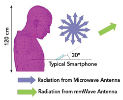
Figure 1 Typical radiation characteristics of mmWave and microwave antennas in a smartphone.
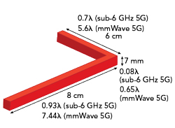
Figure 2 Electrical real estate available within a typical smartphone.
While antennas with multi-frequency functionalities are integrated together, the performance integrity of the sub-6 GHz and mmWave antennas must be maintained. The challenge, with reference to both bands, is to accomplish this in an electrically small form factor, with reference to both the bands. Mutual coupling between the sub-6 GHz and the mmWave antennas must be minimal. The forward gain of the mmWave 5G antenna must be high to support the radio link.
In this article, several design strategies to achieve the aforementioned requirements are illustrated with experimental results.
DESIGN CONSTRAINTS
The reason for multi-octave carrier systems is to enhance the bandwidth allotted per user. Sub-6 GHz antenna systems must be co-designed with the mmWave antenna systems for optimal functionality of smartphone transceivers.1 Typically, the microwave antennas operate at sub-6 GHz frequencies while mmWave antennas function in the 28 GHz bands; specific frequencies depend on the geography and the licensing authorities. The carrier frequency of the mmWave band (28 GHz) is the eighth harmonic of the sub-6 GHz band (3.5 GHz). Hence, co-design of antennas operating in these bands is challenging.2-4
Figure 1 shows the typical use case for microwave and mmWave antennas integrated within the panel of a commercial smartphone. The sub-6 GHz antenna radiates omnidirectionally, in contrast to the unidirectional beam of the mmWave antenna. The beam radiated by the mmWave antenna must be pointed away from the user to facilitate a reliable high data rate link with the nearest base station.
The available real estate on a commercial smartphone is shown in Figure 2. The physical form factor of a sleek smartphone is approximately 8 × 6 × 0.7 cm, which translates to 0.93 × 0.7 × 0.08 λ for the sub-6 GHz band at 3.5 GHz. The same physical form factor translates to 7.44 × 5.6 × 0.65 λ for the mmWave band at 28 GHz.5 The co-designed, or integrated, antenna system must fit within the dimensional constraints of the mobile device without performance deterioration in either band.
The simplest solution for this design problem is a single antenna tuned to both carrier frequencies. The problem is that the antenna will operate quite well in the sub-6 GHz band but its gain and pattern integrity in the mmWave band will be significantly deteriorated. Hence, various multi-port antenna systems are explored in this article.
MULTI-PORT ANTENNA SYSTEM DESIGN EXAMPLES
Example 1
The first antenna system is shown in Figure 3. Port 1 is connected to the mmWave antenna, and Port 2 is connected to the microwave antenna. The same nomenclature is followed for all the designs presented in this article. The mmWave antenna is fabricated on a 20-mil thick Rogers 5880 substrate. It is a corporate inset-fed patch antenna array with a standard half-wavelength separation between elements.6 The radiators are in line with the panel of the smartphone, while the feed network is in the orthogonal plane. This corner-bent antenna exhibits a 10 dB impedance bandwidth of 10 percent (see Figure 4).
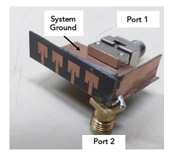
Figure 3 Fabricated prototype of co-design Example 1.
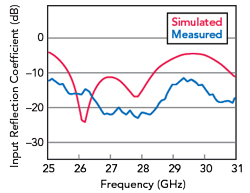
Figure 4 Input reflection coefficient of Port 1 for Example 1.
The electrically close placement of the sub-6 GHz antenna does not detune the mmWave antenna. Unidirectional radiation patterns of the mmWave antenna are shown in Figure 5. The antenna system offers high gain of close to 8 dBi at 28 GHz with minimal back radiation toward the user. The narrow beamwidth is due to the corporate-fed array action of the inset-fed patch antennas.

Figure 5 Radiation patterns of Port 1 for Example 1.
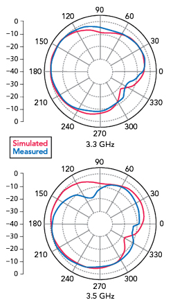
Figure 6 Radiation patterns of Port 2 for Example 1.
Radiation patterns of the microwave antenna within the co-designed ecosystem are shown in Figure 6. These patterns offer omnidirectionality. The slight tilt in the patterns is due to the presence of the system ground of the mmWave antenna. The printed dipole antenna operating at 3.5 GHz detunes slightly due to the electrical proximity of the ground plane.