
Compact antenna designs are necessary for future mmWave 5G smartphones to improve transmit power and battery life. The antennas must have high gain for the available physical aperture and should support orthogonal beams for single hand and dual hand modes. This article gives insight into the design requirements for 5G antennas along with a few design examples to realize these antennas.
R&D investment for 5G design, development and deployment has increased in recent years: for instance, the European Commission has invested €50 million to date with several academic institutions like University of Surrey, TU Dresden, Lund University, etc., have established innovation centers targeted for 5G architecture designs. The Chinese government has initiated IMT-2020 to promote and standardize research in 5G wireless technologies. Leading companies such as Samsung, Qualcomm, Ericsson, Verizon, Nokia Siemens Networks, NXP, NTT Docomo, IBM and Huawei have established dedicated 5G research groups.
Researchers at NYU have performed exhaustive channel propagation studies at 28 and 38 GHz bands to prove the feasibility of mmWave bands for cellular telephony.1 Free space path loss and the penetration losses are relatively high at mmWave frequencies. The free space path loss for sub-6 GHz is in the range of 80 to 95 dB compared to its 28 GHz counterpart that is about 105 to 110 dB. This difference can be compensated for in the gain of the respective antennas on the mobile device-base station link. Path loss can be managed by changing the gain of the antennas with multi-beams, but penetration loss can be as high as 30 to 40 dB for common building materials such as bricks, concrete and glass windowpanes. This aspect deteriorates the link budget severely and the feasibility of maintaining the link budget with decent power at the base station or access point for a given receiver sensitivity has not yet to be implemented.
DESIRED CHARACTERISTICS OF THE SMARTPHONE ANTENNA
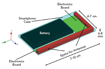
Figure 1 Physical break-down of typical smartphone.
Antennas in the mobile device must have high gain for the available physical footprint. Below is a list of desired characteristics of mmWave 5G antennas.
A. Physical Size
An exploded view of the internal layout of a typical smartphone is illustrated in Figure 1.2 The length of the mobile device is about 7 to 10 cm. Recent trends suggest that the elongation of the smartphone seems to be desired in the market. The width of the smartphone is 4 to 7 cm and the height of the smartphone is about 6 to 8 mm. 5G antenna researchers must incorporate the design into the mobile panel height when designing 28 GHz antennas. They also must co-exist with 4G-LTE and MIMO antennas to support backward compatibility. Most of the real estate is occupied by the battery and the motherboard along with the battery is enclosed in a RF shield. Antenna designers must not meddle with the RF shielding ground enclosing the motherboard as it will compromise the signal integrity of the motherboard. The remaining space must be judiciously used for the front-end and back-end electronics. Therefore, the effective space for all the antennas supporting various wireless services is (8 x 1 x 0.7 cm) along the length of the smartphone and (6 x 1 x 0.7 cm) along the width of the smartphone. When the 5G antenna is independently designed, additional care must be taken for the radiator’s effective area to be within these constraints. For a comprehensive understanding of the mmWave 5G antennas, it is imperative to investigate the effects of co-located antennas, speakers, camera, metal-frame, mold and other electrically close metallic or semi-metallic components.
B. Radiation Pattern
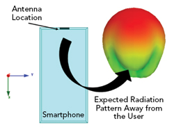
Figure 2 Antenna location on a smartphone.
5G is primarily advertised as a high data rate wireless service, which means that the mobile terminal must be beam locked with the base station beam. This indicates that the radiation pattern of the 5G antennas must always be oriented toward the base station, irrespective of the orientation of the mobile device handled by the user. Details of the implementation are separately presented in the eBook by the authors.3
Figure 2 illustrates the layout for a generic smartphone and the antenna location. The expected radiation pattern when the mobile device is held in the upright position is also depicted in the illustration. Most of the radiated power must be directed away from the user and toward the base station. The beamwidth can be in the range of 80 to 120 degrees. The front to back ratio must be higher than 10 dB when the user holds the mobile device. Hence, the patterns must be engineered to accommodate the user behavior with the mobile device.
C. Beamwidth
In current commercial smartphones, the antennas would be radiating in an omnidirectional pattern for most of the wireless services. The same design process would fail to achieve the link budget in a 5G mmWave context. The beamwidth control can be realized using a phased array approach with individual ports and controllers.
D. Gain
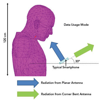
Figure 3 Typical human interaction with smartphone.
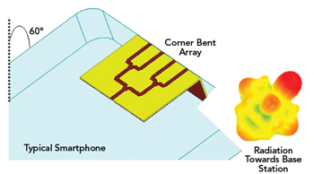
Figure 4 Radiation of a corner bent radiator.
Probably the most discussed parameter in the context of 5G antennas is the gain. A gain of 8 to 15 dBi would be feasible for the constraints of the available space on the mobile device. A gain lower than 5 dBi would indicate a poor front to back ratio sacrificing beam integrity, when the antenna is mounted on the mobile panel. A gain higher than 15 dBi would have a pencil beam sacrificing the angular coverage necessary. As an engineering decision, it is better to have reasonably high gain to maintain the link budget. It must also be noted that the complexity of implementing the antenna module at the mobile terminal must be simpler in architecture and lower cost compared to its counterpart in the base station.
E. Radiation Efficiency
Radiation efficiency above 80 percent is recommended. Efficiency can be high since half wavelength designs could be easily integrated in the mobile device compared to the electrically small antennas of the previous generations. As far as the 5G antennas are concerned, electrically thin low-loss substrate-based designs would lead to high radiation efficiency.
F. Impedance Bandwidth
A 10 dB impedance bandwidth of 26 to 30 GHz is suitable for the 28 GHz band, but specific bandwidth depends on standardization procedures and the regulatory authorities of local geography. Care must be taken so that the antenna has minimal spurious radiation in neighboring bands. Also, 5G antenna designs can afford to have a 10 dB impedance bandwidth due to the feasibility of electrically large designs.
G. Specific Absorption Rate (SAR)
The question of SAR is important for lower bands, especially sub-6 GHz, due to significant penetration of these waves into human tissue. In addition to this, mmWave 5G is mainly intended for data-oriented applications which inherently means that the proximity of the user’s head with the mobile device can be significantly higher compared to voice applications.
The primary issue in designing a hardware ecosystem at 28 GHz is the high free space path loss according to the Friis transmission formula. This phenomenon can be mitigated by incorporating high gain antennas in both the mobile device and base stations to maintain a reasonable communication link budget, a forward gain of 8 to 10 dBi is desirable. Hence, high gain antennas with minimal physical footprint are essential to be integrated in the mobile device. The gain must be almost invariant across the operational bandwidth.
mmWave 5G wireless services are mostly dedicated to data applications. Statistically speaking, the user holds the mobile terminal at an angle of 30 to 50 degrees with respect to the horizontal axis as illustrated in the Figure 3. In this context, the antennas must radiate away from the user to achieve a good link budget. Also, planar broadside radiators would be radiating toward the user where a corner bent design would radiate away from the user as shown in Figure 4. A simpler solution to solve this issue is to integrate end-fire antennas which would radiate mostly away from the user, when integrated with the motherboard of the mobile device, but the effective physical footprint of the antenna would be larger compromising the real estate available in the smartphone.
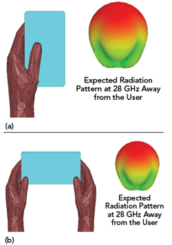
Figure 5 Portrait or single hand mode (a) and landscape or dual hand mode (b).
Wasted space could be attributed to the expected interference from the back-end electronics board at or near the transmission lines feeding the end-fire antenna. The corner bent antenna would occupy minimal footprint post integration with the smartphone casing with radiation toward the base station. Corner bent antennas would have the feeding plane along the plane of the back-end electronics board of the smartphone. The radiator, on the other hand, would be on the panel of the smartphone, as illustrated in Figure 4. A conductor backed radiator would radiate away from the user. It is also interesting to note that when corner bent antennas are integrated with the mobile device, the attenuation caused by the user’s hands is minimal.
mmWave 5G is for data hungry wireless services and not necessarily for voice. When it comes to data usage, the typical data usage modes of the smartphone are portrait and landscape mode, but some users might have a different way of using the phone. The presented cases are generally true for over 80 percent of the use cases. The usage scenario for portrait or single hand mode is illustrated in Figure 5a. In portrait mode, the user uses one of the hands to operate the smartphone. The mmWave 5G antenna for this case must radiate away from the user and toward the base station as illustrated in Figure 2. In addition to the pattern requirement, the antenna must be integrated along the panel of the smartphone to keep interference and mutual coupling to a minimum with the RF board, which is common all the way back to the early mobile phones. The user might use either of their hands during operation and hence the radiation from the antenna must also be operational irrespective of the user’s hand position. To satisfy this criterion, the forward radiating antennas can be installed on the top edge of the phone. The other popular mode is landscape or dual hand mode as demonstrated in Figure 5b.
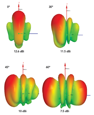
Figure 6 Beam scanning of four element array.
The de-facto industry standard is to implement a phased array, but phased arrays suffer from high scanning loss and would not work when the beams are fired orthogonally.4,5 A single element inset fed strongly resonant patch antenna operating at 28 GHz is initially designed and the same element is extended for phased array operation with four elements with half wavelength spacing. Beam scanning of four-port phased array is illustrated in Figure 6. As evident from the 3D patterns, the beam in the boresight axis is speckle free and gives highest gain of 12.6 dBi. As the beam is scanned away from the boresight, significant gain drop in the beam is observed. When the beam is scanned at 60 degrees and beyond, beam integrity is compromised. The gain drop is close to 5 dB and the patterns become unusable at this scanning angle. The story is identical for an end-fire antenna array as well. Beam scanning for any well-designed phased array is typically limited to ± 40 degrees with respect to the 0 degree axis. A simple solution to solve this issue is to mount two identical phased arrays on the appropriate edges of the smartphone. This method increases the complexity of the controllers and beamformers by at least four-fold. Therefore, the phased array solution might not be as efficient for portrait and landscape mode scenarios as other approaches.