
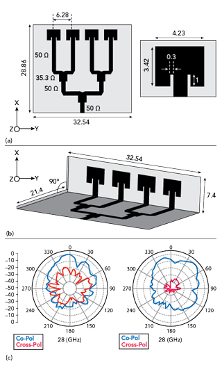
Figure 7 Planar array operating at 28 GHz (a); corner bent array (b); and radiation patterns of the corner bent array in H-plane and E-plane at 28 GHz (c).
MICROSTRIP FED SHARED GROUND DESIGN
A. Compact Array
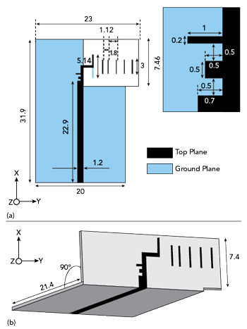
Figure 8 Planar printed Yagi antenna (Units in mm) (a); corner bent Yagi antenna (b).
A wideband phased array antenna operating at 28 GHz is designed and the schematic is shown in Figure 7a.6 The antenna is designed on Nelco NY9220 substrate with a dielectric constant of 2.2± 0.02 and a dielectric loss tangent of 0.0009. The antenna is designed on 0.508 mm thick substrate. The antenna is 32.54 mm wide and 28.86 mm long. The radiators are placed more than 10 mm from the feeding port to minimize interference from the electrically large end-launch connector. The feed line is a standard 50 Ω line. The number of elements is chosen for a desired gain of 8.5 dBi in the boresight. All the four elements are also fed by the 50 Ω transmission lines. To design a wideband transition from the feeding line and the radiators, a corporate feeding network with appropriate quarter wave transformer is used. The spacing between the radiators is optimized for maximum gain in the boresight and found to be 6.28 mm.
The radiator is a standard inset fed patch antenna operating at 28 GHz as shown in the inset of Figure 7a. The planar antenna, when integrated into a smartphone, will radiate toward the user since the beam would be directed that way. Also, the physical footprint of the antenna is high and might be unsuitable for a smartphone application as it is here. Hence, the antenna is corner bent as depicted in Figure 7b. This corner bent or conformal antenna is bent before the radiators, hence the radiation would be away from the user and toward the base station. The actual height of the antenna is 7.4 mm, when this antenna is wrapped around the mold of a typical commercial smartphone the height of the antenna decreases to nearly 6 mm which is compliant with most of the smartphones available on the market today.
The E- and the H-plane radiation patterns are illustrated in Figure 7c. As the beamforming is happening in the YZ plane (H-plane) the beamwidth is narrower compared to the XZ plane (E-plane). The front to back ratio is more than 20 dB across the band of operation, which indicates that when the conformal phased array is integrated onto the smartphone platform, the radiation toward the user is minimal.
B. Compact Yagi Antenna
The wideband corner bent array presented will be operational for portrait mode. Hence the second antenna’s feed line and the beam radiated from the antenna must be orthogonal to meet the requirements of Figure 5. To meet these requirements, a new wideband antenna is proposed, whose schematic is shown in Figure 8a.6 The antenna is 20 mm wide to accommodate the end-launch connector. The antenna is 31.9 mm long and its feed line is 1.2 mm wide feeding the dipole arms, which are orthogonal with respect to the feed line. The feed line is connected to stubs as depicted in the inset of Figure 8a to achieve wide impedance bandwidth. The parasitic radiators aid in gain enhancement. The conformal design of the antenna is shown in Figure 8b. The input reflection coefficient of the corner bent orthogonal antenna is shown in Figure 9 and it operates from 27 to 31 GHz translating to 13.8 percent of impedance bandwidth.
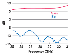
Figure 9 |S11| and forward gain of the corner bent Yagi antenna.
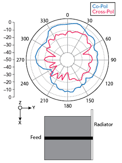
Figure 10 H-plane pattern of the antenna.

Figure 11 Shared ground orthogonal pattern diversity module.
The H-plane (YZ plane) radiation patterns are shown in Figure 10 at 28 GHz. The front to back ratio is more than 10 dB across the band, indicating minimal radiation toward the user post integration with the smartphone. The forward gain is also depicted in Figure 9. The gain is 7 dBi at 28 GHz indicating a high gain for minimal physical footprint.
C. Shared Ground Orthogonal Pattern Diversity Module
The orthogonal pattern diversity module is illustrated in Figure 11. Both the proposed conformal antennas are integrated in the same dielectric with a spacing of 1.2 mm. The integrated antenna would cater to both landscape and portrait modes of a smartphone with minimal physical footprint and minimal radiation toward the user. The input reflection coefficients of the respective ports remain intact despite the closely spaced antennas. The mutual coupling is less than 20 dB across the band. The patterns of the module at 28 GHz are depicted in Figure 12.
VERTICALLY MOUNTED END-FIRE ANTENNAS
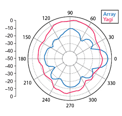
Figure 12 Radiation patterns of the module at 28 GHz.
The schematic of the compact Yagi antenna is depicted in Figure 13a.7 It is designed on Nelco NY9220 substrate with dielectric constant of 2.2. The thickness of the substrate is 20 mil, which is essential to maintain an electrically smaller microstrip trace. Electrically thick substrates would yield higher bandwidths at the cost of increased cross-pol radiation. Initially, a standard microstrip based dipole antenna is designed as shown in the inset of Figure 13a. The dipole arm length is varied to achieve a strong resonance at a higher band, i.e., at 30.5 GHz for a dipole arm length of 5 mm, but the desired band is at 28 GHz. Hence the dipole arms are extended by 0.75 mm on both the planes to tune the antenna to 28 GHz. The parasitics are optimized for gain enhancement of 3 dB in the end-fire. The dipole antenna is fed by a 1.2 mm wide microstrip line through a quarter wave transformer of width 0.5 mm. The arms of the dipole are 0.25 mm wide to achieve impedance matching with the feed line. The width of the ground plane is maintained at 4.8 mm, which is very well within the limits of commercial smartphones assuming a vertical mounting of the presented elements. The width of the ground plane does not hamper the impedance characteristics of the antenna since the insertion loss offered by the electrically compact ground plane is minimal. The width of the ground plane is 20 mm at the feeding edge of the antenna, which is designed for clearance to accommodate the end-launch connector as evident from Figure 13b. The feeding portion extension is a common practice for measurements with end-launch type of connector. SMP or mini-SMA could also be used without the need for extension.
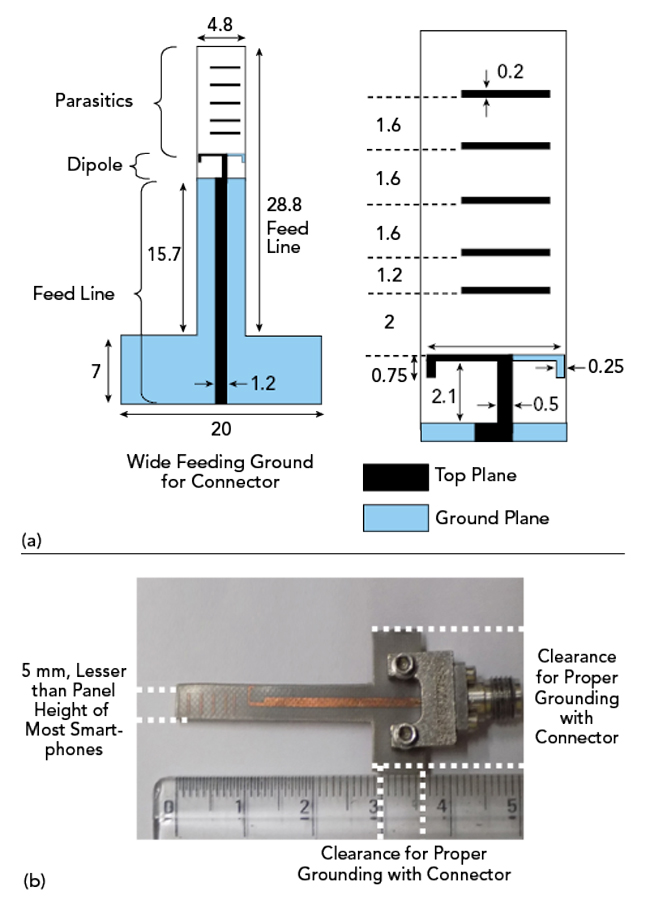
Figure 13 (a) Schematics of the compact printed Yagi antenna; (b) photograph of the fabricated prototype.7
The front to back ratio is more than 10 dB indicating 90 percent more power in the forward direction compared to backward direction. This in turn translates to minimal radiation toward the user when integrated in a mobile device. The cross–polarization level is less than 20 dB. The presented element is placed orthogonally as shown in Figure 14a.
To verify the validity of the proposed architecture, a 3D printed corner piece is designed as shown in the photograph of Figure 14b. The height of the 3D printed panel is around 6 mm with corner tapering, which mimics most mobile phones. In actual deployment scenario, the dielectric used in the commercial mobile case would alter the radiation pattern and impedance characteristics of the antenna minimally as the dielectric is attached to one side of the radiator. The 3D patterns when each port is excited are shown in Figure 14c.
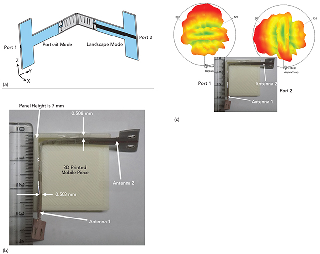
Figure 14 Orthogonal pattern diversity module (a); fabricated prototype with smartphone mockup (b); 3D radiation patterns at 28 GHz (c).6
CONCLUSION
Detailed requirements for future antennas to be integrated in mmWave 5G smartphones and mobile devices are reviewed in this article. The requirements for single hand and dual mode operation are illustrated. Compact antenna module design examples are shown that meet the design requirements with better gain than current patch antennas. More details about “Compact Antenna Designs for Future mmWave 5G Smart Phones” is presented in the eBook by the authors.3
References
- T. S. Rappaport et al., “Millimeter Wave Mobile Communications for 5G Cellular: It Will Work!,” IEEE Access, Vol. 1, 2013, pp. 335–349.
- Y. Huo, X. Dong and W. Xu, “5G Cellular User Equipment: From Theory to Practical Hardware Design,” IEEE Access, Vol. 5, July 2017, pp. 13992–14010.
- Shiban K. Koul, Karthikeya, G.S, Ajay. K. Poddar and Ulrich L. Rohde, “Compact Antenna Designs for Future mmWave 5G Smart Phones,” Microwave Journal, December 2020.
- S. X. Ta, H. Choo and I. Park, “Broadband Printed-Dipole Antenna and Its Arrays for 5G Applications,” IEEE Antennas and Wireless Propagation Letters, Vol. 16, May 2017, pp. 2183–2186.
- J. Shim, J. Go and J. Chung, “A 1-D Tightly Coupled Dipole Array for Broadband mmWave Communication,” IEEE Access, Vol. 7, January 2019, pp. 8258–8265.
- US Patent Application, “Conformal Antenna Module with 3D-Printed Radome,” No. 63033884.
- Karthikeya, G. S., Shiban K. Koul, Ajay K. Poddar and Ulrich L. Rohde, “Ultra‐Compact Orthogonal Pattern Diversity Antenna Module for 5G Smartphones,” Microwave Optical Technology Letters, March 2020, pp. 1–10.