

The microwave antenna was redesigned for this topology to preserve its input impedance characteristics. The actual placement is shown in Figure 7a. It occupies minimal space in the smartphone. The mmWave antenna radiates away from the user in contrast to the microwave antenna, which is connected to Port 2 (see Figure 7b).
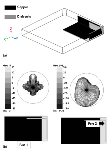
Figure 7 Antenna placement within a smartphone for Example 1: orientation (a) and radiation patterns (b).
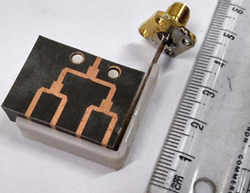
Figure 8 Fabricated prototype of co-design Example 2.
Example 2
The second design approach mounts the mmWave and microwave antennas orthogonally for enhanced isolation between the ports. The fabricated antenna assembly is shown in Figure 8. The corner-bent mmWave antenna array is truncated at the non-radiating edge without hampering its radiating characteristics. The microwave antenna is a simple electrically small, printed monopole resonating at 3.5 GHz. This concept could be generalized with any mmWave antenna with a unidirectional beam and a printed monopole operating in the sub-6 GHz bands.
Example 3
The third design approach employs a shared overlapped ground for both antennas (see Figure 9). A high gain broadside radiator operating in the 28 GHz band is placed on top of its microwave counterpart. The ground plane of the mmWave antenna is common with the printed microwave monopole. The entire ground plane for Port 1 ensures a unidirectional beam. On the other hand, the partial ground plane associated with Port 2 delivers an omnidirectional beam throughout the operating band. Isolation between the ports is greater than 20 dB in both the microwave and mmWave frequency bands. Mutual coupling and the input reflection coefficient for the mmWave band are shown in Figure 10.
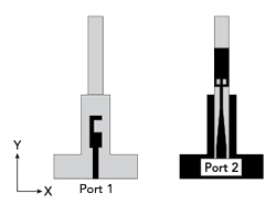
Figure 9 Schematic of co-design Example 3.
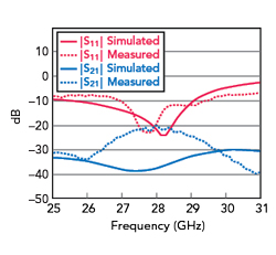
Figure 10 Mutual coupling and input reflection coefficient of co-design Example 3.
Panel mounting is shown in Figure 11. Only one smartphone panel is needed, saving integration space. The 3D-printed smartphone mockup matches the dimensions of a commercial smartphone with a panel height of 7 mm.
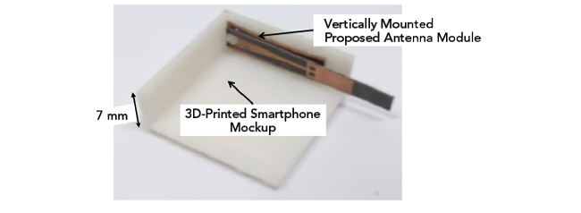
Figure 11 Panel mounting of co-design Example 3.
Example 4
Another uniplanar design technique is to integrate both antennas on a single substrate (see Figure 12). The broadside high gain mmWave antenna is microstrip-fed at one of the substrate edges. The microwave monopole is fed with a microstrip as well, on another edge of the substrate. A small gap of 0.1 mm is introduced in the ground plane to enhance isolation to 25 dB in both frequency bands. The input reflection coefficient and mutual coupling in the mmWave band is shown in Figure 13.
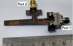
Figure 12 Fabricated prototype of co-design Example 4.
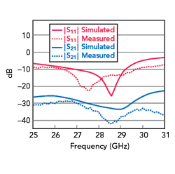
Figure 13 Mutual coupling and input reflection coefficient of co-design Example 4.