Dual-band multi-mode phase shifter MMICs are based on all-pass networks. The 90- and 180-degree phase shifters operate in low-band, high-band and concurrent dual-band modes. The low and high bands are 4.7 to 5.5 and 24 to 27 GHz, respectively, for 5G applications. A phase compensation scheme eliminates phase errors in multi-mode operation. The 90- and 180-degree dual-band phase shifters are fabricated with a 0.15 μm GaAs PHEMT process and have chip areas of 2.7 and 2.9 mm2, respectively, including bond pads. Measurements exhibit very low amplitude imbalance and phase error.
Phased array technology plays an important role in rapidly developing smart wireless systems,1-3 and phase shifters are key building blocks. Multi-functional wireless facilities also need phased arrays that operate over multiple frequency bands.4-6 So, it is cost effective to develop phase shifters that operate over multiple frequency bands, instead of using multiple single-band phase shifters.
This article describes the design, optimization, control and measured performance of 90- and 180-degree multi-mode dual-band phase shifters. The proposed designs provide independently controlled phase states in the 4.7 to 5.5 and 24 to 27 GHz bands, which supports the sub-6 GHz and 24.25 to 27.5 GHz (n258) 5G bands.
MULTI-MODE DUAL-BAND DESIGN
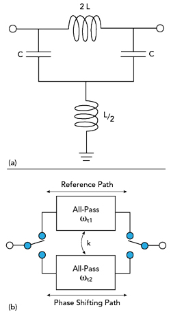
Figure 1 Four-element all-pass network (a) and switched 1-bit single-band phase shifter cell (b).
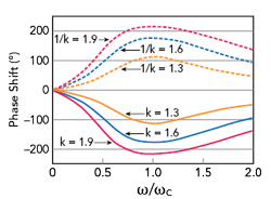
Figure 2 Phase shift of the switched 1-bit single-band phase shifter cell.
Figure 1a shows a two-port, four-element all-pass network.7 When L/C = Z02, |S21| = 1 and |S11| = |S22| = 0. Both ports are matched at all frequencies. The all-pass network has a transition frequency 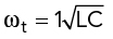 . The component parameters in the network are determined using the equation

A switched 1-bit, single-band phase shifter cell can be realized by combining two all-pass networks with two single pole double throw switches, as shown in Figure 1b. The center frequency, and ωC, and ratio factor, k, are given by


where ωt1 and ωt2 are the transition frequencies of the reference and phase shifting paths, respectively. The phase shift of the single-band phase shifter is given by

dΔφ(ω)/dω = 0 when ω = ωC. Therefore, |Δφ| attains a maximum value at ω=ωC, and

Δφ(ωC) is related only to k according to equation (6). Figure 2 illustrates the phase shift of a switched, 1-bit, single-band phase shifter cell versus normalized frequency and values of k.
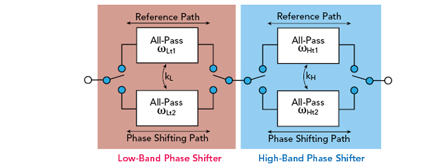
Figure 3 Multi-mode dual-band phase shifter circuit.
A simple multi-mode dual-band phase shifter can be realized by connecting two single-band phase shifter cells in series (see Figure 3). The low-band and high-band center frequencies are given by

respectively (ωH > ωL), where [ωLt1, ωLt2] and [ωHt1, ωHt2] are transition frequencies of the low-band and high-band phase shifters, respectively. The ratio factors of the low-band and high-band are given by

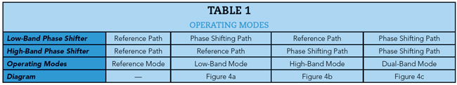
respectively. The relationships between operating modes and selected paths are listed in Table 1.