
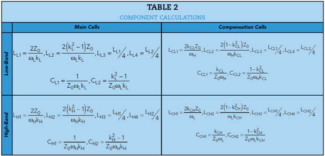
The values of the components in the dual-band phase shifter are listed in Table 2. Phase shifts at fL and fH can be designed to be slightly greater than θd to acquire moderate bandwidth. The 90- and 180-degree dual-band phase shifters were designed and fabricated using a commercial 0.15 μm GaAs PHEMT process. As the PHEMT switches have parasitic on resistance and off capacitance, the component values were optimized to compensate for these parasitics. Both phase shifters were designed to provide independently controlled phase shift in the 4.7 to 5.5 and 24 to 27 GHz frequency bands. To verify the phase compensation technique, the compensation cells were designed to be independently controlled. The 90- and 180-degree dual-band phase shifter designs covered MMIC areas of 2.16 × 1.24 mm (2.7 mm2) and 2.35 × 1.24 mm (2.9 mm2), respectively, including bond pads (see Figure 10).
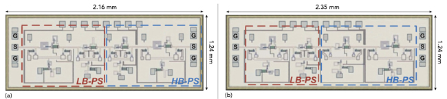
Figure 10 Chip layouts: 90- (a) and 180- (b) degree dual-band phase shifters.
MEASURED RESULTS
The MMICs were measured on-chip using a Cascade Summit 12000M microwave probe testing station and a Keysight N5247A PNA-X network analyzer. Figure 11 shows the measured response and amplitude imbalance of the 90-degree dual-band phase shifter in the reference, low-band, high-band and dual-band modes. The insertion loss in the reference mode was less than 1.7 dB and was less than 2.5 dB in the low-band and high-band modes, respectively. |S11| was better than 13 dB in either band. Amplitude imbalances were less than 0.15 and 0.24 dB in the low-band and high-band modes, respectively.
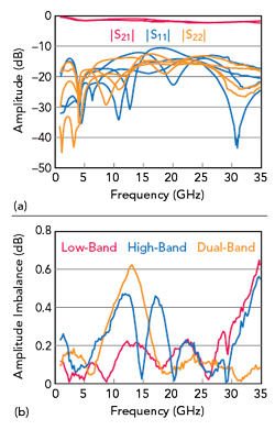
Figure 11 90-degree dual-band phase shifter measured performance (a) and calculated amplitude imbalance (b).
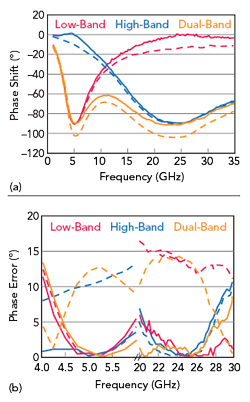
Figure 12 Measured phase shift (a) and calculated phase error (b) of the 90-degree dual-band phase shifter with (solid line) and without (dashed line) compensation cells.
Figure 12 shows the phase shift and phase error of the 90-degree dual-band phase shifter with (solid line) and without (dashed line) the compensation cells. With compensation, the phase errors are less than 2.2 and 2.6 degrees in the low-band and high-band modes, respectively. Without compensation, the phase errors increase to 12.9 and 14.3 degrees in the low-band and high-band modes, respectively.
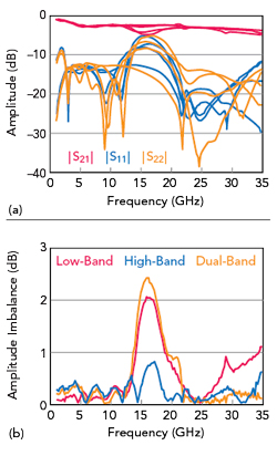
Figure 13 180-degree dual-band phase shifter measured performance (a) and calculated amplitude imbalance (b).
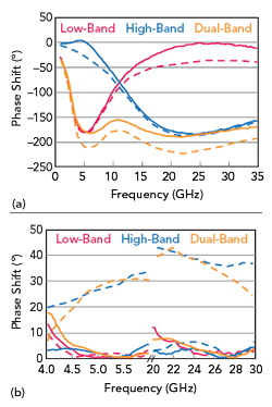
Figure 14 Measured phase shift (a) and calculated phase error (b) of the 180-degree dual-band phase shifter with (solid line) and without (dashed line) compensation cells.
Figure 13 shows the measured response and amplitude imbalance of the 180-degree dual-band phase shifter in the reference, low-band, high-band and dual-band modes. As shown in Figure 13a, measured insertion losses in the reference mode were less than 2.6 dB and 3.4 dB in low-band and high-band modes, respectively. The return loss was better than 12 dB in either band. Amplitude imbalances were less than 0.36 and 0.25 dB in the low-band and high-band modes, respectively.
Figure 14 shows the phase shift and phase errors of the 180-degree dual-band phase shifter with (solid line) and without (dashed line) the compensation cells. With compensation, the phase errors were less than 4.1 and 4.5 degrees in the low-band and high-band modes, respectively. Without the compensation cells, the phase errors increase to 30.8 and 38.2 degrees in the low-band and high-band modes, respectively.
CONCLUSION
Using a commercial 0.15 μm GaAs PHEMT process, 90- and 180-degree dual-band multi-mode phase shifters were designed and fabricated. The phase shifters operate in the 4.7 to 5.5 GHz (low-band), 24 to 27 GHz (high-band) and both bands concurrently (dual-band). A phase compensation scheme eliminates the phase errors in multi-mode operation. Measurements confirmed low amplitude imbalance and phase error. The prototype phase shifters, which support the sub-6 GHz and n258 bands, are good candidates for 5G systems.
ACKNOWLEDGMENTS
This project was supported by the Foundation of Department of Science and Technology of Chongqing (Grant No. cstc2019jscx-zdztzxX0045).
References
- A. Ghosh, “The 5G mm-Wave Radio Revolution,” Microwave Journal, Vol. 59, No. 9, September 2016, pp. 22–36.
- D. Sikri and R. Jayasuriya, “Multi-Beam Phased Array with Full Digital Beamforming for SATCOM and 5G,” Microwave Journal, Vol. 62, No. 4, April 2019, pp. 64–79.
- B. Yu, K. Yang, G. Yang, Z. Qian and C. -Y. -D. Sim, “A 28 GHz Beam Steering Antenna for 5G Cellular Phones,” Microwave Journal, Vol. 63, No. 1, January 2020, pp. 78–86.
- Y. Xiong, X. Zeng and J. Li, “A Frequency-Reconfigurable CMOS Active Phase Shifter for 5G mm-Wave Applications,” IEEE Transactions on Circuits and Systems II, Express Briefs, Vol. 67, No. 10, October 2020, pp. 1824–1828.
- Y. Xiong, X. Zeng and J. Li, “A Tunable Concurrent Dual-Band Phase Shifter MMIC for Beam Steering Applications,” IEEE Transactions on Circuits and Systems II, Express Briefs, Vol. 67, No. 11, November 2020, pp. 2412–2416.
- M. Haroun, H. Ayad, J. Jomaah, M. Cabedo-Fabrés and M. Ferrando-Bataller, “Dual Band Antenna Array for Digital Beamforming in LTE-A and 5G,” Microwave Journal, Vol. 63, No. 11, November 2020, pp. 76–86.
- D. Adler and R. Popovich, “Broadband Switched-bit Phase Shifter Using All-Pass Networks,” IEEE MTTS International Microwave Symposium Digest, July 1991, pp. 265–268.