
Multiphysics simulations capture mmWave circuit performance under realistic operating conditions without performing costly and time-consuming environmental testing. Simulation reduces the number of iterations in the development cycle and expedites design, fabrication and testing.
High speed, high data rate communication is essential for 5G terrestrial and satellite communications, such as broadband via low earth orbit satellites. While massive data transfer via multiple devices is already part of daily life, even greater bandwidth is needed to provide more information through communication channels. This is being accomplished through increased system bus speeds and carrier frequencies; to support this, the operating frequencies of communication systems and components has been migrating from legacy microwave to mmWave.
Higher frequency devices have smaller wavelengths, resulting in reduced device size. Any physical perturbation of such small devices, especially those in resonant circuits, may impact performance through changes in impedance matching, insertion loss and frequency tuning. When a device is designed assuming ideal laboratory conditions is deployed in an operating environment, temperature variation will induce structural deformation. The effects of such environmental conditions, combined with fabrication tolerances, can shift performance outside the design specifications. If these physical effects are included with traditional electromagnetic (EM) component simulations during design, using multiphysics simulation, unexpected results can be identified without performing costly and time-consuming temperature chamber experiments and outdoor field tests. Multiphysics simulations reduce the number of iterations in the development cycle and expedite design, fabrication and testing.
MULTIPHYSICS DESIGN EXAMPLE
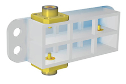
Figure 1 Cascaded cavity filter with 2.92 mm (K) connectors. The front panel is removed to show the interior.
In the following example, the design of a cascaded cavity bandpass filter (see Figure 1) using a traditional EM model adds multiphysics phenomena such as thermo-structural effects using COMSOL Multiphysics® software.1 The filter operates over two mmWave 5G bands: 26.5 to 29.5 GHz for Japan, Korea and the U.S. and 24.25 to 27.5 GHz for the European Union and China. First, a conventional EM model of the cascaded cavity bandpass filter is constructed. This is followed by a structural mechanics simulation including the thermal deformation assuming a uniform temperature distribution, to assess its impact on the frequency response. Finally, a heat transfer simulation analyzes how thermal deformation from a nonuniform temperature distribution affects filter performance.
Cavity Filter EM Model
By solving the vector Helmholtz wave equation derived from Maxwell’s equations (see equation 1), the wave propagation and resonant behavior of the device can be analyzed.

The cavity filter shown in Figure 1 comprises six rectangular cavities in two subsets, loaded by two 2.92 mm K connectors. The two subsets are each connected by inductive irises excited by the K connector coaxial pins and coupled to each other through a coaxial-type structure.
When designing such cavity filters, the initial size of each cavity can be estimated quickly from the resonant frequency of a rectangular cavity structure:

where a and b are the dimension of the waveguide aperture, and d is the length of the rectangular cavity. The frequency for the TE101 mode is chosen. The volume of the metallic domain of the filter and connectors is thick compared to the resonant wavelength, so penetration is not expected. Hence, only the wall surfaces are included in the computation. When metallic surfaces are lossy with finite conductivity and the loss is not negligible, the surfaces can be modeled using an impedance boundary condition. Further simplifying, a certain part of the model can be assumed to be lossless and represented by a perfect electrical conductor. The dielectric part of the coaxial connectors is also assumed to be lossless.
The two coaxial connectors are excited and terminated using coaxial lumped ports, where the reference impedance is 50 Ω. A couple of parameter input files update the cavity geometry, and the U.S. 5G Band (26.5 to 29.5 GHz) and E.U. 5G Band (24.25 to 27.5 GHz) are simulated separately via frequency domain steps. The computed responses shown in Figure 2 show each filter has six poles in the frequency band, corresponding to the number of cavities. With the design for the U.S., Korea and Japan, |S21| is greater than -0.25 dB, and |S11| is less than -17.5 dB. The bandwidth for the E.U. and China is wider than the U.S. bandwidth, which degrades |S11| to -13 dB maximum with |S21| greater than -0.3 dB (see Figure 2b).
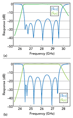
Figure 2 Simulated filter responses for the mmWave 5G bands: Japan, Korea and the U.S. (a) and the E.U. and China (b).
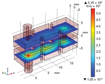
Figure 3 Simulated internal TE101 E-field at 26.15 GHz.
The electric field inside the cavities is visualized in Figure 3. The dominant TE resonance for each cavity is when the frequency is close to the center of the mmWave 5G band for Japan, Korea and the U.S.
Adding Thermal Deformation to the EM Model
The thermal deformation analysis includes the entire aluminum body of the filter and brass connectors, which were not part of the EM-only analysis. To account for simple thermal deformation, the material properties must be updated for other physics phenomena. The dielectric material model in the coaxial connectors includes the coefficient of thermal expansion, Young’s modulus, Poisson’s ratio, density, thermal conductivity and specific heat. For fast prototyping, values are chosen similar to those of FR4. An adhesive layer on one side of the connector body was added to the model. Using the thermal expansion of the linear elastic material addresses the effect of temperature variation on device performance. This includes uniformly different ambient temperatures and their impact when an adjacent component has overheated thermal drift.
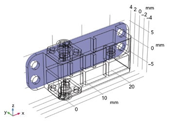
Figure 4 The boundary where the Spring Foundation feature is applied.
As the solid housing body structure shrinks and expands due to temperature change, deformation of the solid part and the cavity air domains must be studied. The electric conductivity of the coating on the cavity walls may also change with temperature. Since structural deformation is involved, a few assumptions are made about the filter attachment to its surroundings. The structure may be firmly connected to a perfectly rigid area, the baseplate, where a small layer of adhesive attaches the filter to the rigid substrate structure. For modeling the connection between the deformed filter and rigid substrate, the COMSOL Multiphysics software Spring Foundation feature gradually transforms the connected part to the deformed state (see Figure 4). The port boundaries sustain the geometry configuration regardless of thermal variations, such as planar and annulus cross sections. These faces are addressed by the two Rigid Connector features in the model, which constrain the boundaries to maintain their shapes and sizes while able to move or rotate due to the deformation.
Three isothermal conditions were simulated: -40°C, 20°C and 120°C. A Moving Mesh defines the deformation of the air domain and a parametric sweep updates the temperature. For each temperature, an EU 5G band frequency sweep was performed. When the temperature decreases, the thermo-structural deformation makes the smaller cavity smaller, shifting the pattern of S-parameters to higher frequencies. With increased temperature, the frequency response shifts down. Overall, the filter bandpass is not severely affected by the changes in geometry due to the thermal change (see Figure 5). Figure 6 shows the structural mechanics analysis at the elevated 120°C temperature.
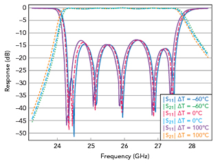
Figure 5 Simulated filter responses with ambient temperature shifts.
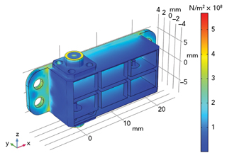
Figure 6 Simulated thermal expansion and von Mises stress with ∆T = 100°C.
Advanced Thermo-Structural Model
With an unexpected heat source in the real world, the temperature distribution of the filter could be nonuniform. This can be computed by solving the heat transfer equation (see equation 3), rather than imposing a fixed uniform temperature deviation.

For the filter design example, assume the plate where the device sits experiences nonuniform heating from some external source. The nonuniform heating is defined as spatially increasing in one direction, distorting the filter and affecting its frequency response. The Heat Transfer in Solids physics interface in COMSOL Multiphysics is applied to all solid domains. The conductive and convective heat flux through the air inside the cavities is not considered, assuming the air is a good insulator. Because the conductive heat path to the baseplate is the most significant, radiation inside the cavities and toward the surroundings is neglected. The thin, high conductivity coatings are not thermally essential, so thermal effects here are also neglected.