
Technical Note
A New Planar Coupled-line Balun for Microwave Applications
This article presents a novel inward collateral coupled-line balun. The new design provides an effective and simple way to avoid the narrow line spacing used in conventional planar Marchand baluns. A new structure with l/4 collateral coupled-lines has been developed to increase by at least ten times the line spacing used in the traditional planar Marchand balun. The measured results show good performance and agree well with the simulated data.
Jwo-Shiun Sun and Guan-Yu Chen
National Taipei University of Technology
Taipei, Taiwan, ROC
Baluns,1 which transform a balanced input transmission signal to unbalanced output signals, are widely used in many wireless applications, such as balanced push-pull amplifiers, frequency doublers,2 antenna feed networks3 and double-balanced mixers.4 The gap between the coupled lines of a conventional Marchand balun is quite narrow5 and difficult to produce in a regular MIC process. This problem can be solved with the new collateral method. Because the structure of a conventional Marchand balun is asymmetric a strong coupling between lines is necessary, leading to narrow spacing. The collateral method consists of connecting a pair of planar Marchand baluns to form a symmetric structure reducing the need for close coupling. Therefore, the line spacing can be wider than for conventional design.
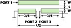
Fig. 1 Conventional Marchand balun.
Numerical and Experimental Results
Because the structure is asymmetric for the conventional Marchand balun, shown in Figure 1 , a strong coupling coefficient is needed requiring a narrow space between lines. An effective and easy way to relax the narrow spacing between the coupled lines of the conventional Marchand balun is proposed. The collateral method can easily solve this problem. The collateral coupled-line balun is a combination of two identical couplers with symmetric coupled-line sections, as shown in Figure 2 . The strong coupling requirement is split between them; therefore, the coupling spacing can be wider than for the conventional design. The simulation of the structured balun, fabricated on an FR4 substrate, was made with Microwave Office 2000.
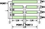
Fig. 2 Collateral inward coupled-line balun.
A traditional Marchand-type balun at 1.8 GHz was designed and laid out with S = 0.007 mm and W = 3 mm. An inward collateral coupled-line balun at 1.8 GHz was designed and laid out with S1 = 0.6 mm, S2 = S3 = 0.2 mm and W1 = W2 = W3 = W4 = 3 mm. The spacings S1, S2 and S3 in the inward collateral balun are increased by at least a factor of ten compared to the traditional Marchand-type balun. This collateral structure can easily be implemented based on conventional MIC technology. It exhibits excellent return loss and balanced outputs.
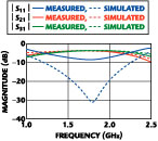
Fig. 3 Simulated and measured S-parameters for the conventional Marchand balun.
Figure 3 shows the simulated and measured results at 1.8 GHz of the traditional Marchand-type balun. The return loss |S11 | is approximately 9 dB and the balanced outputs |S21 | and |S31 | are -4.2 dB. The return loss |S21 | for the inward collateral balun at 1.8 GHz is approximately 29 dB with |S21 | and |S31 | approximately -3.32 dB along with a 180° phase difference, as shown in Figure 4 . The available balanced bandwidth is approximately 450 MHz. Figure 5 is a photograph of the l/4 collateral inward coupled-line balun fabricated on an FR4 substrate. Its size is 40 x 20 mm. The simulated results, obtained by a full wave electromagnetic analysis, are in good agreement with the experimental data.
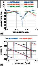
Fig. 4 Simulated and measured S-prarameters for the inward collateral coupled-line balun (a) magnitude and (b) phase.
Conclusion
This article offers a simple and effective way to relax the narrow spacing requirement between coupled lines in the conventional Marchand balun. An inward l/4 collateral coupled-line balun is proposed. The spacing between the coupled lines is greater than ten times the one used in conventional Marchand baluns and can be easily fabricated with conventional MIC processes. The result is a low cost, high performance balun. The simulated results agree well with the measurements.
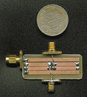
Fig. 5 The collateral inward coupled-line balun.
Acknowledgments
The authors wish to thank Michael Wang, Y.D. Chen and the Wireless Business Unit (WBU) of Quanta Computer Inc., Taiwan, ROC, for their valuable suggestions and encouragement.
References
1. N. Marchand, "Transmission-line Conversion Transformers," Electronics , Vol. 17, December 1944, pp. 142-146.
2. G.D. Vendelin, A.M. Pavio and U.L. Rohde, Microwave Circuit Design Using Linear and Nonlinear Techniques , A Wiley-Interscience Publication, 1990.
3. P. Knott and A. Bell, "Coaxially-fed Tapered Slot Antenna," Electronics Letters , Vol. 37, No. 18, August 2001, pp. 1103-1104.
4. S.A. Mass, Microwave Mixers , Second Edition, Artech House Inc., Norwood, MA 1993.
5. M.C. Tsai, "A New Compact Wideband Balun," IEEE Microwave and Millimeter-wave Monolithic Circuits Symposium Digest , 1993, pp. 123-125.
Jwo-Shiun Sun received his BS degree in electrical engineering from National Cheng Kung University (NCKU) in 1983. After graduation, he served in the army as a communication officer for two years. He received his MS and PhD degrees in electrical engineering from NCKU in 1988 and 1992, respectively. Dr. Sun is currently a professor in the department of electronic engineering at National Taipei University of Technology, Taipei, Taiwan. His research interests are in the field of microwave devices and circuits, microwave dielectric materials, EM-wave and analyses, and satellite mobile communication.
Guan-Yu Chen is currently working toward his MS degree in electronic engineering at the National Taipei University of Technology, Taipei, Taiwan. His research interests include planar antenna and wireless components design.