
Technical Feature
Rigorous Analytical Expressions for Electromagnetic Parameters of Transmission Lines: Coupled Sliced Coaxial Cable
This article is a continuation of a previous article that appeared in Microwave Journal and is the first part in the development of accurate closed-form formulas for the primary parameters (inductance [L] and capacitance [C] matrices) and impedances (Zoe , Zoo ) of the even- and odd-modes for several configurations of transmission lines (sliced coaxial cables, symmetrical band lines and split ring lines). The analytical expressions, deduced from rigorous analysis by the finite element method (FEM)1,2 , method of moment (MoM)3 and curve-fitting techniques, can be easily implemented in CAD simulation tools to design components for wireless communication. This study presents accurate and suitable general expressions for all coupled sliced coaxial cables with a wide range of cut depths and an outer to inner conductor radius ratio between 1.4 and 15. The results of the design of an RF coupler using coupled sliced coaxial cables are presented.
N. Benahmed and M. Feham
University of Tlemcen
Tlemcen, Algeria
|
|
|
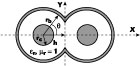
Fig. 1 Cross-section of the coupled line with sliced coaxial cables. |
A directional coupler, using a coupled line composed of two shaped cut coaxial cables, has been analyzed and tested by Djordjevic, et al.3 This type of coupler shows excellent performance in terms of high directivity, very low SWR, good isolation, excellent electromagnetic interference (EMI) shielding, high power handling capability, extremely low cost due to the use of commercial semi-rigid coaxial cables and elimination of a mechanical housing.4,5
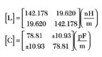
The electrical properties of a lossless coupler using a TEM-mode coupled line can be described in terms of even- (Zoe ) and odd- (Zoo ) mode impedances, and its primary parameter matrices [L] and [C],2
where
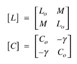
Lo = proper inductance of the isolated line
Co = capacitance of the isolated line
M = mutual inductance of the coupled line
g = coupling capacitance of the coupled line
The cross-section of a coupled line with sliced coaxial cables is shown in Figure 1 .
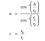
The cable is assumed to be lossless with an inner conductor of radius Rc and an outer conductor of radius Rb .
A material with dielectric constant er fills the inside of the cable. A portion of each cable is cut out and two of these cut cables are used to form the coupled line. The cut depth is represented by h on the cross-section and
H. An, et al. presented formulas only for even- and odd-mode characteristic impedances of the coupled line with a sliced coaxial cable.6 Their expressions, deduced from a FEM analysis, are valid in the ranges
0 ≤ u ≤ 0.99
and
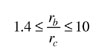
In this article, formulas are offered for the even- and odd-mode characteristic impedances and also the [L] and [C] matrices of the coupled line with sliced coaxial cables having an outer to inner conductor radius ratio

and a cut depth
0 ≤ u ≤ 0.99
These formulas are deduced from an analysis using two coherent numerical methods: FEM and MoM.
|
|
|
|
|
|
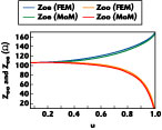
Fig. 2 Even- and odd-mode characteristic impedances as a function of cut depth. |
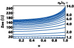
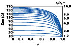
Fig. 4 Even-mode characteristic impedance as a function of cut depth with conductor radius ratio as a parameter. |
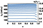
Fig. 6 Inductance as a function of cut depth with conductor radius ratio as a parameter. |
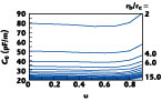
Fig. 8 Capacitance as a function of cut depth with conductor radius ratio as a parameter. |
|
|
|
|
|
|
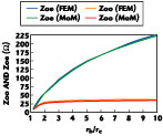
Fig. 3 Even- and odd-mode characteristic impedances as a function of conductor radius ratio. |
Fig. 5 Odd-mode characteristic impedance as a function of cut depth with conductor radius ratio as a parameter. |
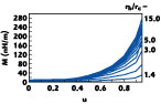
Fig. 7 Mutual inductance as a function of cut depth with conductor radius ratio as a parameter. |
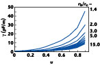
Fig. 9 Coupling capacitance as a function of cut depth with conductor radius ratio as a parameter. |
Numerical Results
In order to validate the numerical results, a structure with an outer conductor radius Rb = 1.49 mm, an inner conductor radius Rc = 0.255 mm and a permittivity er = 1 is studied. Figures 2 and 3 show a comparison between the FEM and MoM results. Through this comparison, it appears that a good agreement is obtained between the two numerical methods.
The FEM results of the even- and odd-mode characteristic impedances and elements of the [L] and [C] matrices, for different values of conductor radius, are shown in Figures 4 to 7 . Odd-mode characteristic impedance and mutual inductance as a function of cut depth is shown in Figures 8 and 9 .
Derivation of Analytical Expressions
Characteristic Impedances
By curve-fitting to the FEM results, it is found that the even-mode characteristic impedance Zoe of the coupled line can be expressed by
Zoe = Zo + b1 u + b2 u2 + b3 u3 (1)
where
Zo = -31.626 + 45.864r - 5.623r2 + 0.354r3 - 0.0085 r4
b1 = 0.862 - 2.982r + 1.841r2 - 0.148r3 + 0.0039r4
b2 = -6.862 + 24.858r - 8.728r2 + 0.690r3 - 0.018r4
b3 = -20.311 + 4.254r + 4.289r2 - 0.404r3 + 0.011r4
and the odd-mode characteristic impedance (Zoo ) is given by
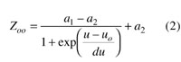
where
a1 = -37.78 + 50.089r - 6.398r2 + 0.417r3 - 0.01r4
a2 = 310.831 - 366.622r + 47.908r2 - 3.263r3 + 0.083r4
uo = 1.407 - 0.017r + 0.0024r2 - 1.507 10-4 r3 + 3.554 10-6 r4
du = 0.153 + 0.0045r - 11 10-4 r2 + 8.483 10-5 r3 -2.21 10-6 r4
Appendix A shows a comparison between the analytical results and those of the literature6 for different values of the cut depth.
Through this comparison, it appears that a good correlation is obtained between these analytical results and those already published.
Inductance Matrix Per Unit Length
The proper and mutual inductances of the coupled line are given by Equations 3 and 4, respectively.
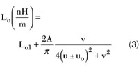
for 1.4 ≤ r ≤ 6
Lo1 = 436.432 - 366.538e-(r-1.4)/3.1212
A = 27.802 - 23.536e-(r-1.4)/2.5891
v = 0.8115 - 0.12441e-(r-2)/2.4837
uo = 0.7396 - 0.140e-(r-1.4)/1.9622
for 6 < r ≤ 15
Lo1 = 585.577 - 437.491e-(r-1.4)/6.3446
A = 31.106 - 21.724e-(r-2)/3.5100
v = 0.84299 - 0.153e-(r-2)/2.7368
uo = 0.75584 - 0.11663e-(r-2)/2.7368
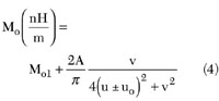
Mo1 = 6.41196 - 9.790r + 2.229r2 - 0.2574r3 + 0.01429r4 - 3.04337 10-4 r5
A = 41.40657 + 28.596r - 1.88142r2 + 0.05831r3
v = 0.35977 + 0.12777e-(r-1.4)/2.0479 + 0.12901e-(r-1.4)/13.71907
for 1.4 ≤ r ≤ 9
uo = 1.05019 + 0.32048e-(r-1.4)/0.748
for 9 < r ≤ 15
uo = 0.52158 + 0.12912r - 0.01035r2 + 2.81944 10-4 r3
Capacitance Matrix Per Unit Length
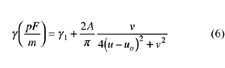
Equations 5 and 6 give the proper and coupling capacitance of the coupled line with sliced coaxial cables, respectively.
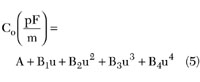
A = 20.49514 + 97.89073e-(r-1.4)/0.4082 + 44.34461e-(r-1.4)/3.25406
B1 = -14.38252 + 8.21613r - 2.11056r2 + 0.26037r3 - 0.01521r4 + 3.38153 10-4 r5
B2 = 8.41414 + 3.64185r - 1.00611r2 + 0.08854r3 - 0.00249r4 - 9.01856 10-6 r5
B3 = -84.99654 + 11.33169r - 0.24693r2 - 0.06647r3 + 0.00411r4 - 3.29262 10-5 r5
B4 = -14.88927 + 61.27891e-(r-0.99433)/19.259 + 67.37928e-(r-0.99443)/1.32918
for 1.4 ≤ r ≤ 7
g1 = -18.10709 + 18.82952r - 8.41344r2 + 1.85398r3 - 0.19828r4 + 0.0082r5
uo = 1.40387 - 0.36507r + 0.17369r2 - 0.04274r3 + 0.00525r4 - 2.54706 10-4 r5
v = 1.01161 - 0.75568r + 0.37576r2 - 0.09433r3 + 0.01168r4 - 5.67111 10-4 r5
A = 386.55698 - 445.76406r + 223.82846r2 - 56.34847r3 + 6.99263r4 - 0.34033r5
for 7 < r ≤ 15
g1 = -0.47174 - 0.47528e-(r-7)/4.4014
uo = 4.00282 - 1.24415r + 0.21668r2 - 0.01879r3 + 8.08443 10-4 r4 - 1.37917 10-5 r5
A = 7.12991 + 16.23608e-(r-7)/9.6403 + 6.11658e-(r-7)/1.78277
Appendix B shows a comparison between the analytical and numerical results for Rc = 0.255 mm, Rb = 0.51 mm, u = 0.7 and er = 1.
The above expressions are valid for airlines. For dielectric filled coaxial lines with dielectric constant of er , the expressions are
C'o = Co er
and
L = Lo
The relative errors between numerical and analytical results are less than 2 peRc ent over a wide range, indicating good accuracy of the closed-form expressions for the coupled line with sliced coaxial cables.
Directional Coupler Design
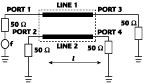
Figure 10 shows the structure of a directional coupler using the coupled line with cut coaxial cables. The parameters of this coupler, operating in the 300 MHz to 3 GHz frequency range, using the coupled line with sliced coaxial cable, are
Zoe = 48.35 W
Zoo = 36.03 W
The features of the coupled line obtained from the proposed formulas are
- Outer conductor radius Rb = 0.51 mm
- Inner conductor radius Rc = 0.255 mm
- Dielectric constant er = 1
- Conductivity s = 5.65 107 (Wm)-1
- Coupler length 1 = 40 mm
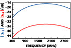
The simulated response of the designed coupler is shown in Figure 11 .
In the frequency range 0.6 to 3 GHz, the coupling is less than 22 dB and the minimum directivity is 17 dB, which permit the designed coupler to have good coupling and isolation over a large frequency range.
|
|
|
|
Fig. 10 Diagram of the directional coupler. |
Fig. 11 Coupling |S12 | and isolation |S14 | of the directional coupler. |
Conclusion
This article presents a set of accurate closed-form formulas for the primary parameter ([L], [C]) matrices and the impedances (Zoe , Zoo ) of the even- and odd-modes for the coupled sliced coaxial cables. These expressions deduced from the FEM and MoM are valid in a wide range of outer to inner conductor radius ratios.
As an application of this study, a directional coupler, operating over a broad frequency range using the coaxial coupled line, has been successfully designed.
|
APPENDIX A | ||||
|
u |
Even Mode |
Odd Mode | ||
|
Zoe ( W) |
Zoe ( W) |
Zoo ( W) |
Zoo ( W) | |
|
0.2 |
76.0745 |
75.29 |
75.2165 |
74.28 |
|
0.4 |
78.7149 |
78.43 |
74.3151 |
73.33 |
|
0.6 |
84.5746 |
84.15 |
71.0909 |
71.40 |
|
0.8 |
96.4674 |
97.2549 |
59.7603 |
58.095 |
|
APPENDIX B | |||
|
Electromagnetic |
FEM |
Analytical |
Errors |
|
Lo (nH/m) |
144.2 |
142.178 |
1.422 |
|
M (nH/m) |
19.96 |
19.618 |
1.743 |
|
Co (pF/m) |
77.68 |
78.8047 |
1.447 |
|
g (pF/m) |
11.12 |
10.9271 |
1.7653 |
|
Zoe (W) |
49.11 |
48.3513 |
1.569 |
|
Zoo (W) |
36.55 |
36.034 |
1.431 |
References
1. N. Benahmed, M. Feham and M. Kameche, "Finite Element Analysis of Planar Couplers," Applied Microwave & Wireless , Vol. 12, No. 10, October 2000.
2. N. Benahmed and M. Feham, "Finite Element Analysis of RF Couplers with Sliced Coaxial Cable," Microwave Journal , Vol. 2, No. 2, November 2000, pp. 106-120.
3. A.R. Djordjevic, D. Darc, M.C. Goran and T.K. Sarkan, Circuit Analysis Models for Multiconductors Transmission Lines , Artech House Inc., Norwood, MA, 1997.
4. H. An, O. Monti, R.G. Bossio and K. Wu, "A Novel Type of Low Cost High Performance Coaxial Cables Coupler," 25th European Microwave Conference , 1995.
5. H. An, R.G. Bossio and K. Wu, "Ultra-wide Band Directional Couplers with Coaxial Cable," Canadian Conf. Electr. and Comp. Eng ., 1995.
6. H. An, T. Wang, R.G. Bossio and K. Wu, "Accurate Closed-form Expression for Characteristic Impedance of Coupled-line with Sliced Coaxial Cable," IEE Proceedings , 1995.