
Even as the current sun spot cycles do not favor radio operation in the HF band (defined here as 1.5 to 30 MHz), there are military and amateur radio applications for 20 W battery-operated radios with whip antennas. In general, the whip antenna which makes the radio portable is not optimized for signal propagation: a whip antenna has no ground return or proper counterpoise. While some users drag a wire up to 8 m behind, this is not an ideal solution.1-2
This article explores optimizing antenna performance for HF and VHF (defined here as 30 to 108 MHz) manpacks using an antenna tuning unit (ATU). Two Rohde & Schwarz battery-operated manpacks with internal ATUs were used for testing, comparing their internal ATUs with the performance obtained using external tuners. The two R&S units are multiband, multirole and multimode software-defined radios (SDR), covering HF and VHF (R&S®MR3000H) and 25 to 512 MHz (R&S®MR3000U, shown in Figure 1). They are similar to other HF, VHF and UHF transceivers popular with radio amateurs.
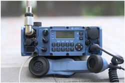
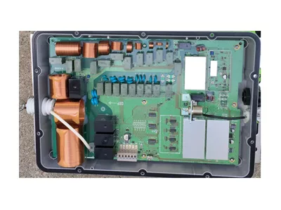
Figure 1 R&S®MR3000U manpack radio, covering 25 to 512 MHz.

Figure 2 Original dipole made by Heinrich Hertz in 1887 used balls at each end to form a capacitive load (Source: Deutsches Museum in Munich).
SHORT ANTENNAS
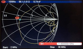
Figure 3 Measured impedance of a 2 x 5 m non-resonant dipole antenna from 2 to 30 MHz.
The first resonant dipole antenna, developed by Heinrich Hertz in 1887, was driven from a “noisy” spark gap transmitter (see Figure 2). Both sides were equally long and used end-loading metal balls, acting as a capacitive device to reduce the length of the two λ/4 resonant segments.3
Now consider a symmetrical, non-resonant dipole, each side 5 m long, with the center point connected to a battery-operated network analyzer approximately the same size and surface area as a manpack. The analyzer is connected to the symmetrical dipole with a mechanically small, 1:1 symmetrical-to-asymmetrical ferrite transformer covering 1 to 60 MHz. Figure 3 shows the measured impedance of the antenna from 2 to 30 MHz, which covers both tactical military and some amateur radio bands. The typical mobile/portable application using a vertical antenna reflects the evolution of the dipole to a monopole: a symmetrical two-wire antenna made asymmetrical with a transformer and best performing with a set of resonant radials and a counterpoise or some kind of grounding.
The magnetic field of the antenna is generated by RF current in the antenna wire or rod, perpendicular to the antenna. The electric field of the antenna is needed for resonance. Many antennas are bent at the end to make them mechanically smaller. An extreme example is the capacitive hat; another is a “loading” coil located about two-thirds of the length - although this reduces the usable bandwidth.
The electrical equivalent of an electrically short antenna is given by
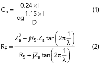
where Ca is the equivalent capacitance of the antenna in pF, D is the diameter of the wire, RF the input-output impedance of the λ/4 antenna, RS the radiation resistance, Za the characteristic impedance of the wire and l the length of the element.
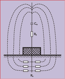
Figure 4 Vertical antenna showing the current loop through the ground.
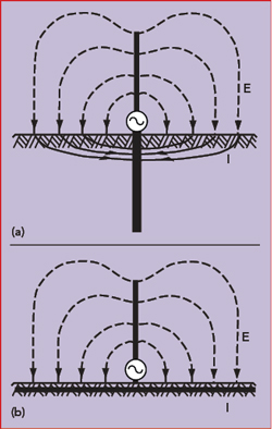
Figure 5 A poor ground near the antenna’s base results in losses from the return current (a), while a ground network or counterpoise reduces the losses (b).4
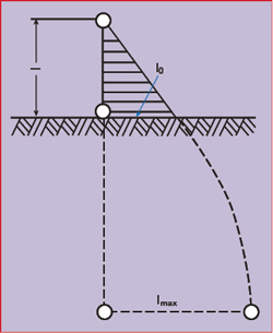
Figure 6 Current distribution in a short antenna, including the ground current.3
Grounding is necessary to close the loop for the currents. Figure 4 illustrates the behavior of the electric field lines for a vertical antenna over ground. The field lines penetrate the surface of the Earth and produce a current that flows back to the ground point, incurring heat losses. The antenna’s efficiency, η, is defined as
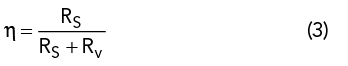
where RS is the radiation resistance and Rv the total effective loss resistance. For electrically short antennas with radiation resistance values of only a few ohms, the resulting antenna efficiency can be very low, especially with long-wave and extremely long-wave communication systems. In such cases, Rv can be reduced with a ground network or a wire network extending over the ground as a counterpoise, especially with unfavorable ground conditions (see Figure 5). All symmetrical antennas not excited with respect to ground, such as dipoles, benefit from the antenna’s independence from the ground resistance - as long as the entire antenna is elevated above the ground.
Electrically short antennas, typically λ/10 or shorter, look like a capacitor with a typical capacitance of 25 pF/m of length, e.g., 75 pF for a 3 m rod. At 2 MHz, where the wavelength is 150 m, an inductor of 84 μH is required for resonance. The radiation comes from the current in the antenna, not from the voltage; the voltage is maximum at the end. To better understand the radiation, consider the case where the whip antenna’s length, l, is λ/4. The vertical radiation pattern of the antenna over ground is1,3
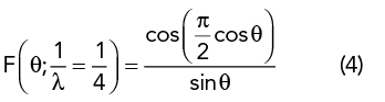
The radiated power, RF current and radiation resistance of the λ/4 antenna over ground is determined from the power radiated in the half sphere. Solving for RS:
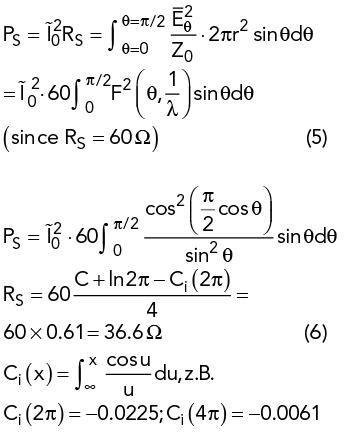
where C is Euler’s constant (0.5772) and Ci(x) is the cosine integral. The radiation resistance of the electrically short antenna based on the electric field can be calculated from:
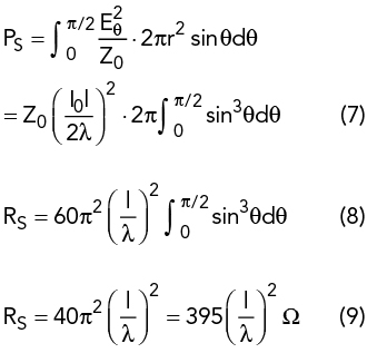
The radiation resistance of the short antenna is obviously very low.
EFFECTIVE HEIGHT
To calculate the effective height of an electrically short antenna, consider that the open circuit voltage, V0, of the antenna is proportional to the antenna field strength, E, where the antenna is located:
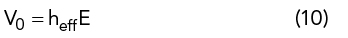
The proportionality factor heff has the dimension of length and is known as the effective height. If the current in the antenna is independent of location (i.e., a Hertzian dipole), then heff corresponds to the antenna’s geometrical length, l. Otherwise, the effective height will be less because of the non-uniform current distribution. In the general case, heff is determined by converting the current area into a rectangle with the same area and the maximum current, I0, at its base (see Figure 6). Its height is then equal to heff. Computationally,
The effective height is related to the effective area, A, and characteristic impedance Z03-4 as follows:
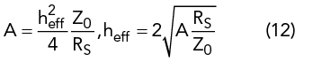
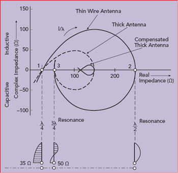
Figure 7 Theoretical input impedance of three wire antennas with different diameters.4
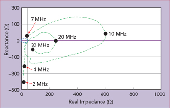
Figure 8 Measured impedance of a 35 ft. whip antenna used on a ship.5
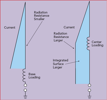
Figure 9 Center loading a whip antenna creates a larger integrated surface for the current than base loading, which improves radiation.6 The two figures are not to scale.
Figure 7 shows the differences in theoretical impedance of wire antennas with different wire diameters. Figure 8 plots the measured impedance versus frequency of a 35 ft. long whip antenna, showing the maximum real impedance is approximately 600 Ω at 10 MHz (λ/2), and the real loss resistor is never below 10 Ω. The imaginary part of the impedance is −400 Ω at 2 MHz and approximately 200 Ω at 9 MHz.
ANTENNA LOADING AND TUNING
Where a whip antenna is loaded affects the antenna’s performance. Figure 9 compares base and center loading. With center loading, both the radiation resistance and integrated surface are larger, which are better for radiation.
The typical lowpass configuration for antenna tuning is a series L, shunt C network, also called a Collins filter (see Figure 10). For the 35 ft. whip antenna operating at 2 MHz (Figure 8), the network needs an inductor of 100 μH and a shunt capacitor of 262 pF. Assuming a 4:1 input transformer and the sum of the radiation and ground loss resistance to be larger than 12.5 Ω (50/4), the tuner only needs two variable elements, and either the left or right capacitor bank in the figure can be eliminated. The right capacitor bank is used when the load resistance is greater than 50 Ω (12.5 Ω using the 4:1 transformer), and the left capacitor bank is used when the load resistance is less than 50 Ω (12.5 Ω using the 4:1 transformer). In this case, at 2 MHz, R = 12 and Xc = −400 Ω, the required series inductor will be 33.42 μH and the left capacitor bank is used to set a value of 3.18 nF. The most inductive impedance is at 9 MHz, approximately 600 +j200 Ω, such that 25 μH and 370 pF are needed for tuning.