
The future of mobile communication will be very different from what we see today, with wireless data traffic projected to increase 10,000 fold within the next 20 years, due to increased usage of smartphones, tablets, new wireless devices and the Internet of Things (IoT). To meet this ever-increasing demand in capacity and to support 5G requirements of greater than 10 Gbps peak and edge rates greater than 100 Mbps for extreme mobile broadband (eMBB) applications, one has to use new spectrum beyond sub-6 GHz frequencies. Due to the availability of large bandwidths at mmWave frequencies, the 5G requirements for eMBB can be met using a simple air interface and high dimension phased arrays. mmWave systems also face inherent challenges, such as high penetration loss, higher sensitivity to blockage and diminished diffraction, which the system must overcome. There are multiple ongoing research and channel measurement activities around the world on 5G mmWave systems, including METIS2020,1 COST2100/COST,2 ETSI mmWave SIG,3 MiWEBA,4 mmMagic5 and NYU WIRELESS.6,7,8 In this article, we examine the practical use of mmWave spectrum for 5G and ultra-dense network deployments.
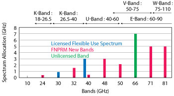
Figure 1 Proposed 5G mmWave spectrum.
Radio spectrum is a scarce resource and is the lifeblood of the cellular industry. 5G will exacerbate the situation, promising a wider range of use cases and related applications, including 8K video streaming, augmented reality (AR), different ways of data sharing and various forms of machine type applications (vehicular safety, different sensors and real-time control) requiring ultra-low latency. Demand for wireless data traffic will probably grow 10,000 fold within the next 20 years, and without suitable new spectrum it will be difficult to make all the promised new use cases and applications happen. The cellular industry is exploring several ways to address these challenges; one promising path is the utilization of underused mmWave frequency spectrum for future 5G networks, coupled with the densification of networks. By their nature, those high frequencies provide much more bandwidth than the spectrum below 6 GHz that is currently being used for mobile communication, and mmWave is more amenable to small cell deployments. Bands having a worldwide primary or co-primary allocation to mobile service have the most potential for spectrum designation. In the United States, the FCC recently published rules which opened up 10.85 GHz of spectrum for flexible use wireless broadband. The rules create 3.85 GHz of licensed flexible use spectrum in the 28 to 40 GHz bands and an unlicensed band from 64 to 71 GHz9 (see Figure 1). The FCC also released a Further Notice of Proposed Rule Making (FNPRM) on the following new bands: 24 to 25, 32, 42, 48, 51, 70 and 80 GHz.9
While mmWave frequencies start around 30 GHz and go through 300 GHz, 5G deployments are expected only up to around 100 GHz. For “low band” mmWave systems with up to a 40 GHz carrier frequency, larger bandwidths can be achieved by aggregating multiple carriers. For example, 10 × 100 MHz carriers can be aggregated to achieve a bandwidth of 1 GHz. Bandwidths from 500 MHz to 2 GHz are envisioned to be realized at mmWave frequencies above 40 GHz without the use of carrier aggregation. The narrow beams operated at these high frequencies impose challenges a mmWave system must overcome; user devices need to be acquired and tracked all of the time, using a narrow beam antenna, while mitigating shadowing with base station diversity and rapid rerouting around obstacles when it occurs.
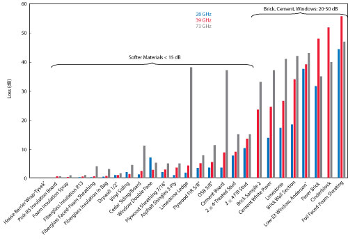
Figure 2 Penetration loss vs. frequency.
5G mmWave systemsare currently targeted to be deployed in the following environments:
- Urban micro (UMi), comprising street canyons and open squares with cell radii less than 100 m and access points (AP) mounted below rooftops
- Suburban micro (SMi), with residential houses in a suburban setting with cell radii around 200 m and APs mounted at 6 to 8 m
- Indoor hotspots (InH), comprising indoor offices and cubicles and indoor shopping malls which are 3 to 5 stories high and APs at 2 to 3 m.
The first step in designing a 5G system at mmWave is to understand the channel characteristics of the above deployment scenarios. Multiple companies, European research consortiums1-5 and academia6 have conducted measurements campaigns for 5G channel modeling, along with ray tracing measurements. The findings of this extensive effort were published at GLOBECOM 2015.10 The measurements indicate that smaller wavelengths introduce increased sensitivity in the propagation models due to the scale of the environment and show frequency dependent path loss and certain large scale parameters. Diffraction, the bending of rays around building corners and roofs, decreases with frequency and is no longer a dominant effect in outdoor channels above approximately 10 GHz. Atmospheric and rain losses are frequency dependent but are small: less than approximately 2 dB for worst-case rain for cell radii less than 100 m, even at 100 GHz. One of the important considerations in channel modeling is penetration loss, which is highly dependent on materials and tends to increase with frequency (see Figure 2).
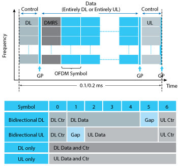
Figure 3 Low latency frame structure for 5G mmWave.
The shadow fading and angular spread parameters are larger and the boundary between line-of-sight and non-line-of-sight depends on the local environment as well as antenna height. The small-scale characteristics of the channel, such as delay and angular spread, and the multipath richness of the channel are somewhat similar over frequency, which is encouraging for extending the existing 3GPP models to wider frequency ranges. The standardization of 5G channel models in 3GPP is complete11 and was primarily based on the GLOBECOM white paper.
5G mmWAVE AIR INTERFACE
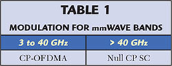
Time division duplex (TDD) is the preferred duplexing method in mmWave cells because it eliminates the need for paired spectrum and is more flexible handling the elastic demand of uplink and downlink traffic. To maximize mobile broadband capacity, the 5G waveforms should be based on cyclic prefix orthogonal frequency division multiplexing (CP-OFDMA) and its variants, like in LTE (4G). 5G mmWave systems will use the same waveforms for both uplink and downlink. For bands above 40 GHz, a single carrier (SC) based waveform is preferred, to maximize power amplifier efficiency and allow efficient beam forming, minimizing switching overhead.12 The promising SC waveforms are null CP SC (NCP-SC) or its frequency domain counterpart called zero-tail OFDM (ZT-OFDM),13 where the regular CPs are replaced with null CPs and has nearly constant envelope properties. NCP-SC modulation is inherently efficient, like LTE’s reverse link,13 which uses DFT-spread OFDM (DFT-S-OFDM). The choice of modulation schemes at various mmWave frequency bands is illustrated in Table 1.
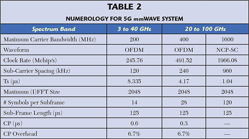
Another important requirement of the 5G mmWave system is to achieve a 10× reduction in the latency of the air interface, compared to 4G. The primary mechanism for meeting this 1 ms latency is the frame structure of the 5G TDD system (see Figure 3). Transmissions are organized into radio frames with 10 ms duration. A radio frame consists of an integer multiple of sub-frames with a predefined number of OFDMA symbols, which depends on the numerology adopted for 5G systems. Three sub-frames types are supported: downlink (DL) only, uplink (UL) only and bidirectional sub-frame. The sub-frame length, in OFDMA symbols, is common for all sub-frame types for a given sub-carrier spacing value. Each sub-frame contains demodulation reference signals (DMRS) for demodulating DL or UL data, DL and UL control and separate reference signals for demodulating broadcast control signals. Both the data and control signals are user-specific beam formed, along with the respective user-specific DMRS. In addition, a dynamic TDD operation can be supported where each sub-frame could be UL, DL or backhaul and can be configured differently from AP to AP. The choice of numerology for 5G mmWave system is guided by channel characteristics and the beam forming methodology at these bands. Smaller cell sizes at higher frequencies and narrow beamwidths imply lower delay spreads and allow shortening the cyclic prefix. Further, short symbol duration with larger subcarrier spacing maximizes beam switching opportunities and enables efficient TDMA control. Finally, the base clock rate of 2N of the base sampling rate used in LTE facilitates multi-mode implementation with LTE and simplifies implementation. Table 2 provides some example numerology based on the above principles.
MASSIVE MIMO
Massive multiple-input-multiple-output (MIMO) is the extension of traditional MIMO technology with a few controllable antennas (typically less than eight) to antenna arrays having a large number of controllable antennas (16 or more). At mmWave, the number of antenna elements at the APs can vary from 128 to more than 1,000. The main benefit of massive MIMO is the enhancement in both capacity and coverage. At sub-6 GHz frequencies, the system is more interference limited, and capacity-enhancing solutions with massive MIMO single user (SU) and multi user (MU) MIMO become essential. At mmWave, coverage-enhancing solutions are essential to compensate the higher path loss at these frequencies. To provide the desired wider area coverage from a single radio and antenna, the antenna system needs to dynamically steer the beam to the user devices inside the cell coverage area.
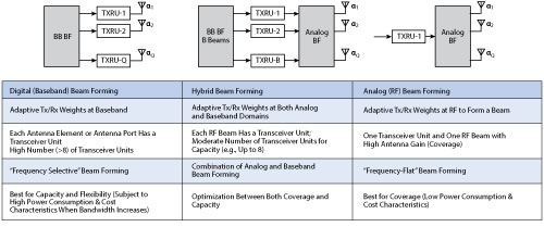
Figure 4 Baseband, RF and hybrid architecture properties for massive MIMO.
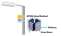
Figure 5 Access point with inband backhaul.
Of the variety of means to steer antenna beams, the most attractive for this frequency band is an electronically steered array (ESA), also referred to as a phased array. Phased arrays require active phase—and often amplitude—control of the antenna elements. The small wavelength at mmWave frequencies implies that the antenna elements of a phased array will be closely spaced, and the supporting circuitry is well served by modern, highly integrated monolithic microwave integrated circuits (MMIC). The phased array is envisioned to provide a wide field of view, somewhere between 90 and 120 degrees azimuth range; elevation coverage range is expected to be smaller in many applications, although the design should not preclude a range comparable to azimuth. The size of the array will vary with the deployment scenario or application, i.e., it will depend on the desired system gain. The phased array architecture must therefore support scalable solutions in which multiple phased array MMICs and antennas can be combined to form larger or smaller arrays.
Phased arrays can be designed around various RF architectures, particularly the phase and amplitude steering and combining of the antenna element signals. Phase steering can occur at baseband, RF or a combination of baseband and RF, known as a hybrid architecture (see Figure 4). Having a full digital baseband unit behind each antenna provides the most flexibility but requires the most hardware, particularly analog-to-digital and digital-to-analog converters. Because the converters consume a large amount of power at the higher bandwidths of mmWave, the RF or hybrid approaches are more likely for first-generation 5G mmWave systems.
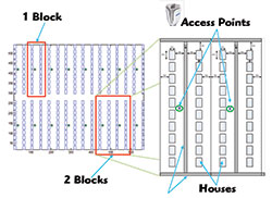
Figure 6 SMi layout with 320 houses.
mmWave APs and integrated wireless backhaul will fit in small boxes that are easy to install on lamp posts, walls or small masts (see Figure 5). This concept is suitable for both the UMi and SMi environments.
To overcome high diffraction and penetration losses and blockages at mmWave frequencies, a cluster network concept is envisioned where a set of coordinated APs work together to provide ubiquitous coverage through AP diversity. In the event of blockage due to shadowing, one AP will rapidly hand off the user device (UD) to another AP in the cluster. These handoffs may be quite frequent as the UD moves through the network. Moving obstacles, hand motion and changes in orientation may all contribute to multiple, successive handoffs. mmWave APs can also be deployed with a sub-6 GHz overlay using LTE-Pro and/or 5G new radio (NR) to provide dual connectivity to both systems. With dual connectivity, the user can be simultaneously connected to both systems, so that the radio link connectivity is maintained even if the mmWave system is blocked.
The performance of the mmWave system is simulated in a SMi environment with varying numbers of antenna elements and different values of penetration loss. The neighborhood layout in Figure 6 shows a suburban grid with 16 blocks and 20 houses per block, totaling 320 houses. There is one AP per block and 10 active customer-premises equipment (CPE) per AP site. Figure 7 shows the downlink user and edge throughput at 39 GHz with 800 MHz bandwidth, as the number of AP antenna elements per polarization is varied from eight to 128, and the number of antennas at the CPE is fixed to two. The figure shows that:
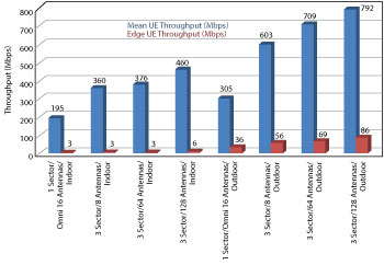
Figure 7 Full buffer DL mean user and edge throughput for various SMi environments at 39 GHz with 800 MHz bandwidth.
- Using outdoor CPEs, the network approaches the desired 500 Mbps UL, 500 Mbps DL mean CPE throughput
- Larger antenna arrays and sectorization at the APs improves performance significantly. Performance using indoor CPEs at 39 GHz is challenging due to the high penetration loss.
PROOF OF CONCEPT
Several proof of concept (PoC) mmWave systems were developed to prove the theoretical work and gain further knowledge about how a mmWave system behaves in the field. A first version, shown at Mobile World Congress 2015, used a steerable lens antenna and demonstrated tracking of moving users. A bidirectional system operating at 73 GHz with a 1 GHz bandwidth, it achieved a peak throughput of 2.3 Gbps using single input, single output (SISO). The design supports IP bearer data with a one-way latency of less than 1 ms. It was field tested in outdoor and indoor environments in Japan and the U.S., with peak throughput exceeding 2 Gbps and a maximum range of 160 to 200 m. At Mobile World Congress 2016, Nokia demonstrated the next version, a unidirectional 15 Gbps system incorporating 2-stream MIMO in a 2 GHz bandwidth.
As a next step, the antennas were miniaturized to better match the expected phased arrays used at both the AP and UE. At the 2016 Brooklyn 5G Summit, Nokia demonstrated beam scanning using a phased array at 60 GHz with the 1 GHz bandwidth system. Because the element spacing decreases with higher frequencies (~ 2.5 mm at 60 GHz), an 8 × 8, λ/2-spaced antenna array could easily fit into an area smaller than 20 sq mm, as shown in Figure 8. A fully integrated 16 element, 90 GHz phased array ASIC was developed at Nokia Bell Labs, and the ASIC die was assembled directly on an organic PCB substrate that housed the patch antennas. The integrated array demonstrated an EIRP of 34 dBm at 90 GHz and a receiver noise figure of 7 dB per element. The system can establish multi-gigabit wireless links at distances of tens of meters. This low cost, integrated solution does not require any waveguide components or expensive materials and follows a traditional die-on-PCB assembly process.
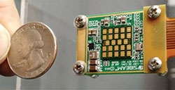
Figure 8 12-element phased array showing the small size of the array. Source: SiBeam Inc.
Nokia is pushing spectral efficiency to get the most capacity out of the spectrum, demonstrating spectrum efficiencies up to 100 bps/Hz at 28 GHz. This will make wireless transmission of large data files far more economical than what is currently achievable. The prototype uses a novel physical layer technology, including massive MIMO, that guarantees huge system capacity and spectral efficiency. It achieved a peak transmission rate of over 50 Gbps across a short range, while supporting latency requirements as short as 250 µs. At that speed, a 50 GB movie can be downloaded in less than eight seconds.
Conclusion
The use of mmWave spectrum in wireless communication is considered revolutionary, and this article examines the state-of-art in mmWave communication for the wireless industry, covering spectrum options, channel characteristics, air interface design and massive MIMO architectures. Proof-of-concept systems have been developed and are essential to show how the challenges of a mmWave system can be overcome. The next step is commercial deployment, with first trials of specific 5G use cases in early 2017. Ideally, a simple and low cost small cell solution, using a fully flexible baseband technology, massive MIMO and phased arrays at mmWave will be feasible by the year 2020. This solution will help achieve the promise of 5G and the many new applications and use cases it will enable.
Acknowledgment
The author would like to thank Nokia colleagues for their help in preparing this article and National Instruments for their support with the 73 GHz Proof-of-Concept system.
References
- METIS2020, Deliverable D1.4 v3, “METIS Channel Model,” July 2015. www.metis2020.com/wp-content/uploads/METIS_D1.4_v3.pdf.
- COST, www.cost2100.org/.
- ETSI, “New ETSI Group on Millimetre Wave Transmission Starts Work,” www.etsi.org/news-events/news/866-2015-01-press-new-etsi-group-on-millimetre-wave-transmission-starts-work.
- MiWEBA, Deliverable D5.1 “Channel Modeling and Characterization,” June, 2014, www.miweba.eu/wp-content/uploads/2014/07/MiWEBA_D5.1_v1.011.pdf.
- mmMagic, 5g-ppp.eu/mmmagic/.
- T. S. Rappaport et al., “Wideband Millimeter-Wave Propagation Measurements and Channel Models for Future Wireless Communication System Design,” IEEE Trans. Communications, Vol. 63, No. 9, pp. 3029–3056, September 2015.
- T. S. Rappaport et al., “Millimeter Wave Mobile Communications for 5G Cellular: It Will Work!,” in IEEE Access, Vol. 1, pp. 335–349, 2013.
- G. MacCartney et al., “Indoor Office Wideband Millimeter-Wave Propagation Measurements and Channel Models at 28 GHz and 73 GHz for Ultra-Dense 5G Wireless Networks,” IEEE Access, October 2015.
- FCC Spectrum Frontiers (mmW) Order on 28/37/39/64-71GHz and Further Notice of Proposed Rulemaking (FNPRM): transition.fcc.gov/Daily_Releases/Daily_Business/2016/db0714/FCC-16-89A1.pdf.
- 5G Channel Model White Paper, Globecom 2015, www.5gworkshops.com/5GCM.html.
- 3GPP TR38.900, www.3gpp.org/ftp//Specs/archive/38_series/38.900/38900-100.zip.
- Amitava Ghosh et al., “Millimeter-Wave Enhanced Local Area Systems: A High-Data-rate Approach for Future Wireless Networks,” IEEE Journal on Selected Areas in Communications, Vol. 32, Issue 6, June 2014.
- Stephen Larew, Timothy A. Thomas, Mark Cudak and Amitava Ghosh, “Air-Interface Design and Ray Tracing for 5G Millimeter Wave Communications,” Proceedings of IEEE Globecom Workshop, 2013.