Many system integrators are recognizing the increasing number of commercial and consumer applications for the millimeterwave frequency spectrum. Applications like automotive radar, local area and last-mile communication systems, portal security systems, traffic control infrastructures, and UAVs have encouraged those in the millimeter-wave industry to address the manufacturing costs of V-, E- and W-Band − and even higher frequency bands − devices, components and subassemblies. RF performance testing for products is one key part of the manufacturing process and often requires expensive test equipment that drives up costs. While many test equipment leaders continually introduce new test equipment that pushes frequencies higher, noise figure measurement systems are still limited to 50 GHz or lower.
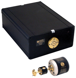
SAGE Millimeter has introduced a series of full waveguide band noise figure and gain test extenders (STG series) to extend industrial standard noise figure test equipment to 50 GHz and higher. Figure 1 illustrates how the noise figure and gain test extender interfaced with standard test equipment. According to the diagram, the noise figure and gain test extender consists of two parts: the full band downconverter (STC series) and the full band noise source (STZ series).
The function of the downconverter is to convert high millimeter-wave frequency (50 GHz or higher) by mixing it with a low frequency signal (20 GHz or lower) to produce IF frequency which can be measured by a low frequency analyzer or receiver (10 MHz to 1.6 GHz for example). The downconverter includes many high performance SAGE Millimeter components, such as a Faraday isolator (STF series), full band balanced mixer (SFB series), waveguide filters (SWF series), passive and active multipliers (SFP and SFA series) and an IF low noise amplifier (SBL series). While the standard model offers 10 dB input noise figure based on direct downconversion technique, the advanced model with integrated millimeter-wave low noise amplifier is offered as an option to further improve the input noise characteristics. A typical gain versus frequency of an E-Band downconverter is shown in Figure 2, demonstrating very flat gain performance.
Figure 1 Interface block diagram.
The full band noise source is a silicon IMPATT diode-based solid state noise source. The noise source implements high performance diode and proprietary circuit designed to yield high ENR with extreme flatness in the entire waveguide bandwidth. While the standard model offers moderate ENR, the model with higher ENR up to 20 dB is also available as an option. The noise source integrates a Faraday isolator at its output to further improve the port VSWR, resulting in a more stable and reliable noise figure measurement. A typical ENR versus frequency of an E-Band (60 to 90 GHz) noise source is shown in Figure 3. From the curve, very flat ENR figures across the entire E-Band are observed. The flat ENR level is highly desired for any measuring system.
Figure 2 Downconverter gain versus frequency.
Figure 3 Noise source ENR versus frequency.
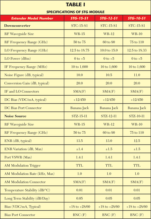
Table 1 shows the main electrical and interface specifications of the featured noise figure and gain test extenders. The RF interface of the extenders is equipped with standard waveguide. SAGE Millimeter’s SWC series waveguide to coax adapters can be used to convert the interface to 1 mm coaxial interface.
In addition, the standard extenders can also be tailored to offer lower input noise figure, higher ENR or various conversion gain options.
SAGE Millimeter Inc.
Torrance, Calif.
(424) 757-0168
info@sagemillimeter.com
www.sagemillimeter.com