
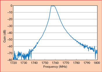
Figure 1 MP3 agile filter, tuned for a 3 MHz bandwidth.
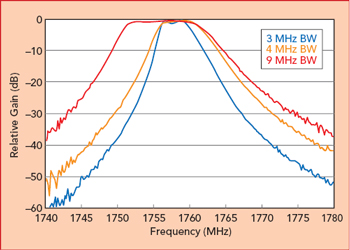
Figure 2 MP3 agile filter, tuned for varying bandwidth.
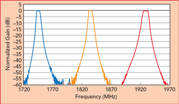
Figure 3 MP3 agile filter, tuned across a 10 percent frequency range and with a 5 MHz bandwidth.
A new filter technology has been developed that is tunable in frequency, with variable bandwidth and the capability to operate at RF through mmWave frequencies. These filters exploit new innovations in regenerative resonance circuits that result in high stability and controllable Qs in the thousands. Further, the self-calibration circuitry ensures ease of configuration in a wide range of applications. A multipole filter has been demonstrated with variable bandwidth and tunable passband. The demonstrated filter has a bandwidth of 2.8 MHz (0.16 percent) centered at 1.75 GHz and is comprised of three dominant poles with Qs on the order of 1900. The core of this filter technology is a regenerative resonator, denoted as the ATL3. Three ATL3s have been combined to realize an agile multipole Chebyshev bandpass filter. An important feature of the ATL3 architecture is orthogonal control of center frequency and bandwidth (Q) that results in superior stability and ease of control. This technology is compatible with semiconductor integration and an ideal candidate for 5G systems, IoT and a wide range of military systems.
A 3-pole tunable bandpass filter has been demonstrated, denoted as the MP3, which consists of three regenerative resonators. Figure 1 shows a measurement of the MP3, tuned for a nominal 3 MHz bandwidth, centered at 1758 MHz. The passband ripple is less than 0.8 dB. Since the filter is comprised of three independent electronically adjustable poles, the passband ripple and transition steepness are programmable. Figure 2 shows an example where the bandwidth is varied, from a nominal 3 to 4 and 9 MHz. Low ripple is maintained. Note that the gain in Figure 2 is normalized. The poles feature Q enhancement via regeneration, as explained in more detail later in this article.
Bandwidth can be adjusted by moving the frequency of the poles and by adjusting Q. The MP3 can implement a third-order bandpass filter of arbitrary pole placement. Hence any Chebyshev filter type can be realized with the usual trade-off of ripple versus transition steepness. In the other extreme, a Butterworth type filter can be implemented with maximally flat passband, but less transition steepness.
The poles may also be moved together in frequency, which allows the filter to be tuned up and down in frequency. Figure 3 shows an example of the filter tuned over a 10 percent bandwidth, 185 MHz, from 1745 to 1930 MHz. The range of frequency tunability is 15 percent and is limited by the details of the prototype circuit design of the resonators, and much larger tuning ranges are possible with straightforward design variations.
Background
Regeneration was a common technique in early RF circuits, about 100 years ago, as a means to achieve higher gain given the vacuum tubes available at the time. It was also found that this regeneration could increase selectivity, enhancing the Q of tuned circuits.1-2 Regeneration is no longer in wide use, thanks to the high gain available from modern devices, and due to the challenges of controlling circuits that operate at or near instability. More recently, Q enhanced filters have been demonstrated on silicon, making use of regeneration.3-4 This work made use of one active pole and one passive resonator, and stable Q enhancement was limited.
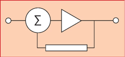
Figure 4 Basic regenerative circuit.
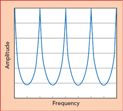
Figure 5 Response of the basic regenerative circuit in Figure 4.
Basic Principles
The inherent frequency selectivity of a regenerative circuit can be understood by considering a simple positive feedback loop, as shown in Figure 4. This circuit will result in a periodic response in frequency, as shown in Figure 5, where the period is determined by the delay around the loop, and the throughput gain is determined by the gain in the loop. This response, with its periodic resonances and infinite set of poles, is not generally desired. A simple modification can be made to realize a single dominant resonance as shown in Figure 6. A resonator is inserted into the loop which suppresses higher harmonics, passing only the fundamental. The dominant pole of the feedback regenerative loop is adjustable by varying the delay around the loop and by tuning the resonator. The Q of this regenerative resonator can also be adjusted by changing the loop gain.
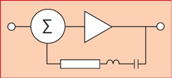
Figure 6 Incorporating a resonator in a regenerative circuit.
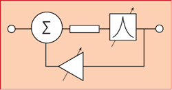
Figure 7 A tunable regenerative circuit with variable Q.
The delay and the gain can be anywhere in the loop, so this concept has considerable circuit flexibility, depending on system and circuit requirements. The circuit in Figure 7 has a tunable resonator in the forward path, and adjustable gain in the feedback path. This gain is equivalent to negative resistance and can compensate for the loss of the resonator in the forward path. This allows a wide range of effective Qs to be realized. When there is no feedback, the resulting Q is that of the resonator on its own. As gain is increased, the loss of the resonator can be completely compensated, and any further increase in gain results in oscillation.
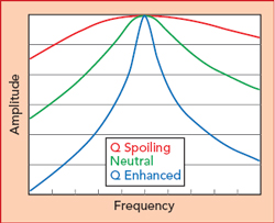
Figure 8 The Q in a regenerative circuit can be adjusted by changing loop gain.
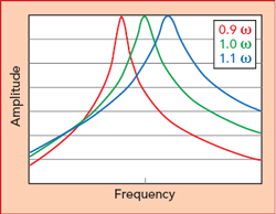
Figure 9 The resonant frequency of a regenerative circuit can be changed by adjusting loop delay and tuning the resonator.