
Low Cost Electronically Scanning Antennas for Wireless Communications Applications
Paratek Microwave Inc.
Columbia, MD
Success in today's fixed wireless communications market depends on many factors. From a technology perspective, systems today and in the future will be required to adapt to broadband dynamic needs, requiring systems that can support rapid allocation of bandwidth, high reliability and availability and be cost-effective.
A new family of DRWiN™ (Dynamically Reconfigurable Wireless Networks) electronically scanning antennas addresses these three parameters. The new antennas can double link distance, nearly double capacity and, with some of the highest gain in the industry, ensure five nines availability at competitive prices.
IMPROVED SYSTEM PERFORMANCE
Link budget issues such as range, capacity and coverage are significantly improved using the DRWiN antennas. The additional gain of the scanning antenna directly translates to additional link range. The 28 dBi gain model is approximately 10 dB higher in gain than current fixed solutions, thus leading to more than double the range. Additional gain also mitigates the effects of rain fade on the link distance.
Increased gain can also be used for increased capacity. Higher throughput can be provided to users by switching from lower order modulations, such as quadrature phase-shift keying, to higher order modulations, such as 16 quadrature amplitude modulation or higher. Significant capacity improvements are also achieved through adaptive null steering for interference cancellation. The improved signal quality enables tighter frequency reuse patterns, resulting in increased capacity.
Having 10 dB of additional gain not only ensures excellent line-of-sight coverage at millimeter-wave frequencies, but also enables non-line-of-sight coverage for low end voice services through building reflection. This capability increases the number of subscribers that can be served by a single basestation, and directly translates to an increase in revenue for service providers.
ANTENNA FEATURES
The DRWiN electronically scanned antennas feature adaptive beam patterns that provide a narrow beam for high gain and a wide beam for acquisition. The beam patterns are software controlled and can be rapidly hopped from one direction to the next.
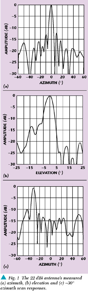
Antennas are available from 20 to 40 GHz. Two examples are a 22 dBi gain version and a 28 dBi model designed to operate over the 27.5 to 28.5 GHz frequency range with a scan range of ±45°. The 22 dBi model's beamwidth is specified at 6° in azimuth and 5° in elevation, while the 28 dBi version has an azimuth beamwidth of 3° and an elevation beamwidth of 2°. The first sidelobe response is 12 and 13 dB for the 22 and 28 dBi models, respectively. Figure 1 shows the 22 dBi model's measured response and Figure 2 shows similar data for the 28 dBi antenna. Both versions feature linear vertical polarization and a csc2 elevation pattern. The RF interface is WR28 with an SWR of 1.4 max.
|
|
|

APPLICATIONS
In a typical application scenario utilizing commonly deployed antenna systems, the antenna, in the broadcast mode, sequentially transmits permission for each subscriber to communicate, then listens for a response. Each broadcast is spread uniformly across the entire sector and thus, the antenna's total radiated power is diluted over the entire scan volume (typically 90°). Most of the energy is wasted on subscribers that are being told "it's not your turn yet."
The DRWiN antenna focuses all of the radiated power into a small volume directed at the selected subscriber to provide higher data rates, greater throughput or longer range. The antenna's beam can then be refocused on each subscriber requiring service in any random sequence. It can then revert back to a broad coverage to acquire subscribers requesting new service.
The DRWiN antennas also reduce interference from outside noise sources using their ability to "look away" from the noise source. Whereas fixed beam antennas continuously listen to the entire sector, a noise source anywhere in the sector will significantly degrade or even shut down communications over the entire sector. The DRWiN antenna can simply switch to a narrow beam and avoid the source of noise while continuing to provide service to the remainder of the sector, thus resulting in greater system up time.
One additional benefit of the DRWiN antenna is that multiple beams may be operated independently at the same frequency within the same sector. This capability further increases capacity by providing service to multiple customers simultaneously at maximum throughputs.
CONCLUSION
A new family of electronically controlled passive phased-array antennas has been introduced that can significantly improve network capacity, reliability and noise discrimination. The DRWiN antennas provide rapid beam hopping to a broadband wireless network and can be a flexible network solution in an ever-changing communications environment.
Paratek Microwave Inc., Columbia, MD (443) 259-0140.
Circle No. 305