
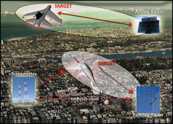
Figure 1 Passive radar working principle.
Passive sensors do not emit electromagnetic waves, but exploit those produced by sources of opportunity (FM radio signals, telecommunications equipment, other radars, etc.). They are therefore compatible with the environment (do not generate additional electromagnetic pollution) and can also operate in close proximity to residential areas and, more specifically, in an urban environment. In addition, passive sensors face the erosion of the electromagnetic spectrum due to the widespread of telecommunications equipment and carry out effectively the surveillance function, not only for the purposes of military defense, but also for homeland security. Furthermore, passive sensors operate in a covert manner and are not subject to electromagnetic interference or intentional threat, surviving where an active sensor may fail its mission.
AULOS, SELEX Sistemi Integrati’s new green system, is the result of many years of R&D, some undertaken in concert with the Terrestrial Armaments Department of the Italian Ministry of Defense (MoD). AULOS is a technologically advanced sensor developed entirely on the basis of a “soft radar” approach, involving signal sampling directly at carrier frequency using commercial-off-the-shelf (COTS) devices for signal reception and digital processing. There are plans in the immediate future to develop, in the mobile version, the digital terrestrial television as a ready-made source for use alongside the frequency modulation (FM) radio signal. The resulting bi-band system will offer great flexibility for potential use in a variety of operating conditions and will increase the estimation of the target position.
A passive radar, usually referred to as passive covert radar (PCR) or passive coherent location (PCL), is considered “passive” because it does not have its own transmitter but exploits one or more transmitters of opportunity located somewhere in the countryside. This means that a passive radar does not add a single millijoule to the RF energy already present in the environment. It is a receiving equipment designed to detect and track targets illuminated by one or more broadcast stations, for example, FM radio, digital audio broadcast (DAB), and digital video broadcasting television (DVB-T). Figure 1 depicts the passive radar working principle.
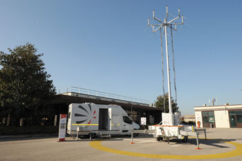
Figure 2 Mobile passive radar developed in SELEX Sistemi Integrati.
Though the principle of passive radar has been known for decades, it has only recently been of growing interest to research laboratories, universities and industries interested in passive locations. The reason is related to the technology achievements of the last few years, mainly in the field of digital electronics. Today, powerful computers and fast, high-dynamic, digitizers are available on the market for relatively low prices.
Passive sensors may be adopted in a number of applications, most notably for surveillance and environmental protection. Passive sensors may be used to monitor airports, ports, critical infrastructure (for example, power stations and water plants) and information media stations. When it comes to coastal surveillance, passive radars are still expected to offer a number of advantages in terms of eco-compatibility and sustainability. In fact, they can be installed even in protected and previously restricted areas reasonably, without giving either environmental groups or the residential population reason for concern. Moreover, passive radars may be employed as a gap-filler for traditional surveillance systems (for example, coverage beyond 20° elevation) or as an adjunct to air traffic control, particularly for small aircraft without sophisticated instrumentation. It can also be used to monitor commercial and military air traffic up to a distance of several hundred kilometres, and follow targets with very small radar cross-section values compared to normal radar frequencies, when enhanced through the use of FM bandwidth.
SELEX Sistemi Integrati has completed the testing of two prototypes of fixed passive radars operating in the FM band1-3 and has started the integration activities of a mobile passive radar hosted in a motor home using FM source of opportunity (see Figure 2). The mobile system has been designed to do the following:
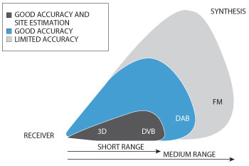
Figure 3 Accuracy and detection range of the analyzed frequency bands.5
- Allow the reception and processing of FM signals (under integration).
- Allow the reception and processing of DVB-T signals4 for future development.
- Move and deploy an antenna array on a telescopic pole.
- Host comfortably more than one operator.
- Control power supply.
- Host the human machine interface between the operator and the passive radar.
Rationale of Multi-band Development
The goal of a radar sensor is to obtain a long detection range, large volumetric coverage (in elevation) and excellent range and angle resolution (related to the instantaneous bandwidth of the signal). To maximize the performance of the passive radar, the following sources have been taken into consideration:
- FM band
- DVB-T band
- DAB band
DAB (190 to 230 MHz) is an international standard for digital broadcasting for mobile reception. DAB allows a channel to distribute multiple radio networks and provides the received signal absolutely free of noise and interference.
Figure 3 shows a simplified volumetric coverage that can be obtained using DVB-T, DAB and FM as a source of opportunity for passive sensors. Table 1 qualitatively synthesizes the expected performance of the passive sensors operating on the different bands.
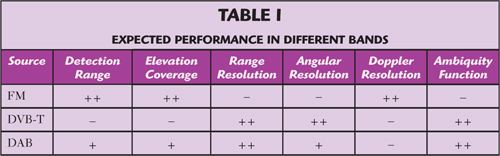
From the analysis of Figure 3 and Table 1,it is easy to understand the choice to develop a system that combines dual-band characteristics of FM and DVB-T in the future. The resulting sensor will combine the best features of the analyzed frequency bands, thus achieving long-range detection and fine range and angular resolution. Future research items will then be related to a dual band (FM and DVB-T) mobile radar equipped with two circular arrays (uniform circular array [UCA]) having half wavelength dipoles as radiating elements. One of the arrays will be devoted to the FM band and the other to the DVB-T band. The system will be based on a digital beamforming (DBF) technique and it will employ the contemporaneous reception of multiple sources of opportunity.
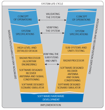
Figure 4 Simplified V-model of AULOS.
System Design Drivers
High Level System Requirements
Passive radar deals with weak echoes for detecting small targets, making it necessary to acquire several RF channels using a MIMO receiver with a good trade-off between sensitivity and dynamic range. Direct sampling of the FM band helps to reduce the complexity and the cost of the receiver, but requires a hardware platform able to manage and process the associated high data throughput. In-line (real-time) pre-processing of the signals for implementing multiple digital down conversions (DDC) and fractional resampling helps to select and forward the data associated to the frequency bands of interest to the radar processing. The different algorithms used for the pre-processing and the radar processing require heterogeneous processing elements: FPGAs, GPPs and GPUs.
AULOS project has pursued an integrated product and process development (Concurrent Engineering6), where the design modularity has made a major contribution to product flexibility and the sharing of the engineering process for designing and testing the radar subsystems and units (see Figure 4). It also accelerated the transition between system life cycle phases because of heavy hardware and software reuse, thereby reducing the total cost and shortening time-to-market.
Hardware Solution
Not only did the National Instruments (NI) PXI platform meet the adaptability needs of the design, but it delivered the high quality timing and synchronization capabilities required to simultaneously sample the FM stations. Moreover, NI offers a wide selection of PXI RF front ends to cover multiple RF bands and the ability to move the data between all the instrumentation hosted in a chassis at a real-time rate for covering multi-channel acquisition and in-line signal processing by FPGA.
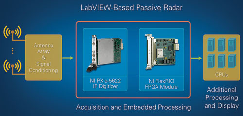
Figure 5 Architecture of the software defined receiver.
The sampling of the signals coming from the antenna was performed using the high-dynamic range and wideband NI PXIe-5622 high-speed digitizer. Then, thanks to the high data throughput of the PXI Express chassis (more than 800 MB/s per slot), the data was moved to an FPGA for performing the DDC. In this manner, the seamless integration of the digitizer and FPGA provides the software defined receiver (SDR) implementation for AULOS9,10 (see Figure 5). Finally, the data is transferred to the powerful additional signal processing unit, based on CPU or GPU elements, for implementing the radar processing algorithms to detect very weak echoes from the target that are deeply buried in the noise.
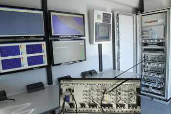
Figure 6 Hardware platform integration on PXI platform.
Software Solution
The AULOS project faced a programming challenge for:
- Implementing an SDR, which deals with multiple acquisition channels and multiple DDCs.
- Having benefited from heterogeneous computing (GPP, GPU, FPGA) for the complex algorithm implementation.
- Pursuing anintegrated product and process development.
Graphical system design methodology, such as the one offered by NI LabVIEW system design software, was one approach for handling this programming challenge. NI’s approach to graphical system design helped the project team reuse software and hardware from design to prototyping to deployment of the passive radar system (see Figure 6).
Use of Graphics Processing Unit for Signal and Data Processing
In this section, the work done for mapping the passive radar signal and data processing on GPU-based devices is briefly reported. M. Bernaschi et al. provides many more details on the subject.7,8 The total amount of data received by a typical processor of a passive radar can vary between 0.5 and 1 Gbit/s, depending on the number of sources and the desired time for processing. This huge amount of data must be handled in real time, possibly using the most compact and least energy consuming hardware system available. It has been demonstrated that the combined use of GPU and CPU is the best suitable solution for combining performance and power consumption.8 In fact the following observations were made:
- The use of CPU cores allows the efficient management of flow control and the implementation of mainly serial pieces of code.
- The use of GPU cores allows the execution of intrinsic parallel code as fast as possible with low power consumption and frees CPU cores to be used in other tasks.
- The integration of the entire system becomes easier. A 16 Core Intel Xeon processor and one or two nVidia GeForce GTX 580 are able to solve the computational problem for the combined use of FM radio and DAB-DVB-T signals.
- Power consumption decreases to the minimum.
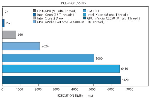
Figure 7 Comparison among execution time for different implementations of the entire PCL processing.
Figure 7 compares the performance of different computational devices as an example of the achieved results. The execution time of typical PCL processing chains (adaptive interference cancellation, formation of range-Doppler maps and CFAR) has been selected for comparison purpose.
The most convenient approach in the implementation of signal processing for modern PCL systems turns out to coincide with the most common way used nowadays in developing calculus intensive software: the hybrid approach. This kind of approach uses the GPU cores only for the algorithms that can exploit the high parallel computational power of the GPU devices. The CPU, on the other hand, is used for the intrinsically serial algorithms and for all the code that requires a high level of complexity.
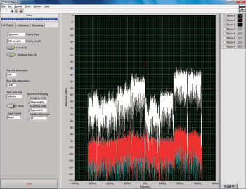
Figure 8 Spectrum of multiple DVB-T transmitters in the receiver.
Conclusion
The current RF signal reception and acquisition technology makes it possible to implement SDR for passive radar detection. Thanks to the wideband and high dynamic range of high speed digitizers, the sampled FM signals are processed using an FPGA that performs the in-line signal channelization. The whole platform was integrated in an NI PXI chassis, delivering a compact form factor for design and deployment in mobile stations. All the critical, real-time software components are implemented in LabVIEW. Also, the technology makes it possible to receive and process multiple channels of DVB-T transmitters providing more accurate target detection and localization (see Figure 8).
References
- A. Benavoli, A. Di Lallo, A. Farina, R. Fulcoli, R. Mancinelli, L. Timmoneri and L. Chisci, “Design and Development of a Signal and Data Processor Test Bed for a Passive Radar in the FM Band,” 2007 IET International Conference on Radar Systems, pp. 1-5.
- S. D’Alterio, A. Di Lallo, A. Farina, R. Fulcoli, R. Mancinelli and L. Timmoneri, “Design and Development of a Soft Real Time Signal-Data Processor and Presentation Test Bed for a Passive Radar in the FM Band,” 5th Multi-National Passive Covert Radar Conference (PCR-2007).
- A. Di Lallo, R. Fulcoli and L. Timmoneri, “Real Data Performance Evaluation of Adaptive Spatial Co-Channel Cancellation for Passive Covert Radar,” 2008 XIV Riunione Annuale CeTeM / V Workshop AIT.
- F. Canini, A. Di Lallo, L. Timmoneri and D. Vigilante, “Use of Digital-Television Terrestrial (DTV) Signals for Passive Radars,” 2010 International Radar Symposium Digest, pp. 1-4.
- D. Poullin et al., “3D Location of Opportunistic Targets Using DVB-SFN Network: Experimental Results,” 3rd FHR Focus Days on PCR– May 3-4, 2011.
- INCOSE, “System Engineering Handbook”, v.3.2.1
- M. Bernaschi, A. Di Lallo, R. Fulcoli, E. Gallo and L. Timmoneri, “Use of Graphics Processing Unit for Passive Radar Signal & Data Elaboration,” 3rd FHR Focus Days on PCL, May 3-4, 2011.
- M. Bernaschi, A. Di Lallo, R. Fulcoli, E. Gallo and L. Timmoneri, “Combined Use of Graphics Processing Unit (GPU) and Central Processing Unit (CPU) for Passive Radar Signal & Data Elaboration,” 2011 International Radar Symposium Proceedings, pp. 315-320.
- B. Eged and B. Babjak, “Universal Software Defined Radio Development Platform,” 2006 NATO RTO IST, Symposium on Dynamic Communications Management.
- B. Eged, “Software Defined Radio Technology for Radar Systems,” 2009 NATO RTO SET-136, Specialist Meeting, Invited Keynote Lecture.