
Long-term evolution (LTE) is one of the 4th generation (4G) mobile communication technologies developed at different frequencies ranging from 400 MHz to 4 GHz with bandwidths up to 20 MHz.1 LTE technology facilitates multiple antennas performing both transmit and receive operations, (such as multiple-input-multiple-output (MIMO) to support high data rate applications. However, integrating several antennas onto a printed circuit board (PCB) becomes progressively more difficult as each new generation of handsets experience miniaturization (that is thin, slim shapes). The closely-spaced antennas produce high mutual coupling, which opposes the relatively low correlation between the received signals as required for effective MIMO performance. High port-to-port isolation is required to achieve the low correlation between closely spaced antennas.
Various techniques to improve the isolation include: placing parasitic elements between driven elements,2 using suspended inductive wire connecting the array elements at appropriate locations3 and using a shunt reactive element in combination with certain length of transmission line.4 The aforementioned methods are unattractive because of the space requirement for the parasitic elements, inductive wire and the transmission line. Orthogonally polarized elements may offer significant port isolation, but the finite-sized ground plane generates high cross-polar components that spoil the polarization purity. Other techniques to achieve port-to-port isolation include using decoupling branch line hybrids.5 Research has also been conducted to develop diversity antennas by combining the separate antennas into one, thus reducing the space requirement and achieving polarization as well as pattern diversity
Keeping the modern day miniaturization concept in mind, this article presents a compact antenna design that minimizes the space requirements and still achieves low correlation. The antenna design emerges from orthogonally oriented antennas that can be excited separately as well as together, as introduced by Rao and Wang.6 A more compact design with a novel feeding structure that suits modern, miniaturized handheld devices is presented. Suitable polarization and pattern diversity can be achieved because of the orthogonal orientation of the antennas.
Antenna Design and Optimization
Cell phones and handheld devices are the new media centers, with access to music, photos, games, video and a host of connectivity options. Cellular standards such as High Speed Packet Access (HSPA) are already enabling multi-call capabilities on handsets, but the demand for mobile broadband services continues to rise. Therefore, a technology is needed that will suit the needs of different network operators that have different bandwidth allocations and also allow operators to provide different services based on spectrum. LTE technology with fast, mobile, multimedia data services appears to address critical issues at the optimal time and in a cost-effective manner. The goal of LTE is to increase the capacity and speed of wireless data networks, while exploiting MIMO concepts to achieve ambitious requirements. MIMO employs multiple antennas on both the transmitter and receiver to transmit additional data by utilizing persistent multi-path effects rather than causing interference. However, the challenge faced in a MIMO system is the placement of multiple antennas with low correlation (high isolation) in a finite given space on the platform. In addition, the modern day telecommunications are marching towards smaller, faster and more portable handheld devices and this trend makes the task of the engineer even more challenging.
Incorporating multiple antennas on a handheld device is difficult because of the miniature size, which imposes high correlation if the antennas have poor isolation. Therefore, an electrically small antenna (ESA) that can offer low correlation is needed. An ESA is an antenna that satisfies the condition,7 ka <0.5, where k is the wave number 2π/λ, and a is the radius of the minimum size sphere that encloses the antenna. Keeping in mind the present day miniaturization of the handheld devices, a dual-port ESA has been designed, as shown in Figure 1. Unlike the printed inverted-F antennas (PIFA), the miniaturization is achieved by introducing slots in the radiating elements of the dual-port ESA.
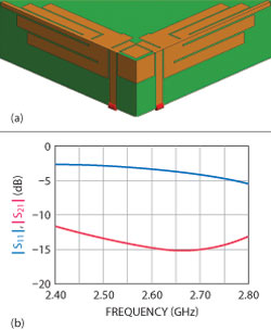
Fig. 1 Electrically small dual-port antenna: (a) antenna design and (b) S-parameters.
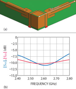
Fig. 2 Self-resonant dual-port ESA: (a) optimized CSA and (b) S-parameters.
The input impedance of an ESA is characterized by low resistance and high reactance. The radiation resistance decreases with the size causing the antenna reactance to dominate. Although offering the ability to improve the efficiency of an ESA, matching circuits are not an option for two reasons. First, the challenge of designing a matching circuit that is also electrically small. Second, the restricted size of the handheld device that offers little room for additional circuits. Therefore, a self-resonant ESA should be designed to match standard transmission lines while still offering good port-to-port isolation. Figure 2 shows a self-resonant ESA, which is an optimized version of Figure 1, with better matching and isolation. The ESA condition for the optimized antenna is ka =0.49 (<0.5).
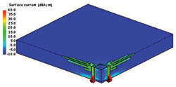
Fig. 3 Surface current distribution of the dual-port ESA.
The commercial software FEKO8 has been used throughout the ESA analysis and design stages. The Simplex (Nelder-Mead) and Particle Swarm Optimization (PSO) algorithms were used for the optimization.9 The Simplex algorithm, a local optimizer, converges much faster compared to the PSO, a global optimizer. However, the success of the Simplex depends on the starting point that carries the disadvantage of converging at a local minimum. The chance of achieving the global minimum, without compromising on speed, has been improved by hybridizing the PSO with the Simplex. The global optimizer will be used to find the starting point for the local optimizer.
Even though both radiating elements of the dual-port antenna are physically connected, the novel feed provides the required isolation. A clear current null can be observed from the surface current distribution of the ESA, as shown in Figure 3.
Similar to the diversity antenna designed by Rao and Wang,6 the dual-port ESA can be used in three different configurations:
- Both ports act as two independent transmitters (or) receivers (or) one port will be receiving while the other is transmitting.
- One port is excited while the other is shorted or loaded with matching impedance.
- One is excited while the other is left open for a switch diversity application. If the signal level falls below a threshold in this configuration, the receiver switches to another branch in search of a better signal.
Figure 4 shows the radiation pattern of the dual-port ESA in three configurations.
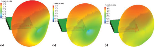
Fig. 4 Radiation pattern of the dual-port ESA: (a) two ports are excited, (b) one is excited, the other short and (c) one is excited, the other is open.
Mobile Handset
The dual-port ESA can be used for MIMO applications, specifically with cell phones (for its size) to implement LTE in order to reach the 4G standards. Figure 5 shows the antenna in a handset and the radiation pattern from the handset close to a head. The radiation pattern from the handset is near spherical when placed close to the head, which is the desired pattern for cell phone applications. In mobile telecommunications, the channel capacity (bit rate performance) of the MIMO system, which is the driving force of the LTE technology, is as important as the impedance and radiation characteristics of the mobile handset.
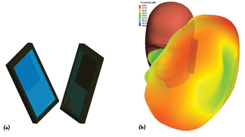
Fig. 5 ESA in a handset: (a) front and back view of the handset and (b) radiation pattern of the handset when placed close to a head.
Channel Capacity
The performance of wireless communication systems fundamentally depends upon the mobile radio channel. As a consequence, predicting the propagation characteristics as well as further performance indicators, such as the channel capacity between the transmitting and receiving antennas of the wireless system, is one of the most important tasks for the radio planning of LTE networks.
The mobile radio channel in urban and indoor areas is characterized by multi-path propagation. Dominant propagation phenomena in these scenarios are the shadowing behind obstacles, the reflection at the walls of buildings, the wave guiding effects (due to multiple reflections) in street canyons or corridors and the diffractions at vertical and horizontal wedges. As deterministic ray tracing models can cope best with such propagation effects, the prediction of the channel capacity is based on a ray tracing wave propagation simulation. The propagation model is fully three dimensional and computes all rays with up to three interactions (including double diffractions and combinations of reflections and diffractions). The prediction of the path loss along the ray is computed with the uniform theory of diffraction (UTD) and with Fresnel coefficients for the reflections. In order to accelerate the time-consuming path determination, the Intelligent Ray Tracing (IRT) Model10,12 can be utilized.
However, the main disadvantage of deterministic wave propagation models is their excessive computation time. The most time-consuming part is the determination of all relevant paths between transmitter and receiver. To avoid large computation times, the IRT Model is used to predict the SISO channel impulse response between the centers of the transmitter and the receiver antenna arrays. As the spacing between the antenna array elements is rather small, the same propagation paths are assumed to exist for all antenna array elements and only the signal phases are changing from one element to the other (assuming planar incidence of the waves).11 Considering such a modular approach avoids re-computing the ray tracing between all the antenna elements of the transmitter and the receiver station during the generation of the MIMO channel matrices, which are required for the computation of the channel capacity according to the well known Shannon formula.11
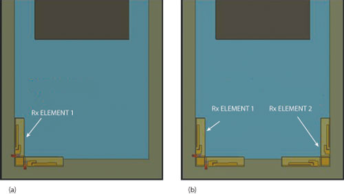
Fig. 6 Handset with location of receiving elements: (a) 1×2 LTE system with one receiving element and (b) 2×2 LTE system with two receiving elements.
In the following subsections, the channel capacity is evaluated for LTE systems in urban and indoor environments using different MIMO configurations in the 2.6 GHz frequency band. The first configuration considers two antenna elements at the base station and one dual port ESA at the mobile handset. The second system uses the same base station equipment, but two dual port ESAs at the lower corners of the handset, as shown in Figure 6. In both examples, the dual-port ESA operates in configuration-II, where one port is excited while the other is shorted or loaded with matching impedance.
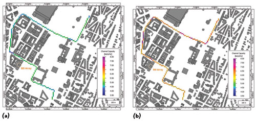
Fig. 7 Channel capacity along a receiver trajectory in an urban environment: (a) 1×2 LTE system and (b) 2×2 LTE system.
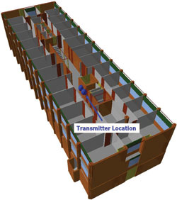
Figure 8 Multi-floor office building with the transmitter location.
In the urban environment, the handset moves along a trajectory of length 2.2 kilometers, as shown in Figure 7. The base station antenna array is located 15 meters above the street level on top of a building, where the signal is radiated from a uniform linear array consisting of two antenna elements with a spacing of ten wave lengths. The average channel capacity along the route is 4.8 and 6.4 bit/s/Hz for the 1×2 and the 2×2 systems, respectively, which clearly shows the benefit of utilizing the MIMO technology within the mobile handset.
Besides the urban environment, a modern multi-floor office building was also selected for the evaluation of the channel capacity. Figure 8 shows the three-dimensional view of the considered indoor environment. The location and orientation of the base station antenna array (blue balls) are depicted as well.
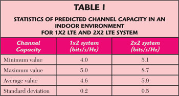
Figure 9 depicts the predicted channel capacity using the same equipment for the base station as well as for the handset as already introduced for the urban environment. An average channel capacity of 4.6 and 5.9 bit/s/Hz is achieved for the 1×2 and the 2×2 systems, respectively, on the upper floor of the building. Some further statistics are listed in Table 1. With an average capacity increase of 1.3 bit/s/Hz, the 2×2 LTE system offers a clear advantage regarding data throughput compared to the 1×2 LTE system.
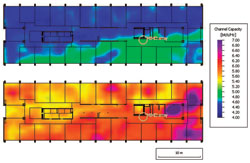
Figure 9 Channel capacity in an indoor environment for a 1×2 LTE system (top) and a 2×2 LTE system (bottom).
Conclusion
This article gives a complete workflow of an antenna design for LTE mobile phone applications, starting from the antenna design to the bit rate channel capacity calculations. The antenna is a dual-port ESA with a novel feeding structure that can be used in three different configurations for the LTE mobile phone applications. The dual-port ESA displays good radiation characteristics when embedded into the mobile handset as well as the handset placed close to the human head. The MIMO analysis is done using the Intelligent Ray Tracing Model to calculate the channel capacity of the mobile handset in both the urban and indoor environments.
References- S. Sesia, I. Toufik and M. Baker, LTE – The UMTS Long Term Evolution: From Theory to Practice, Wiley, Chichester, U.K., 2009.
- K.G.Y. Ding, Z. Du and Z. Feng, “A Novel Dual-Band Printed Diversity Antenna for Mobile Terminals,” IEEE Transactions on Antennas and Propagation, Vol. 55, No. 7, July 2007, pp. 2088-2096.
- G. Park, et al., “The Compact Quad-Band Mobile Handset Antenna for the LTE 700 MIMO Application,” 2009 IEEE International Antennas and Propagation Symposium Proceedings, pp. 1-4.
- S. Chang, Y.S. Wang and S.J. Chung, “A Decoupling Technique for Increasing the Port Isolation Between Strongly Coupled Antennas,” IEEE Transactions on Antennas and Propagation, Vol. 56, No. 12, December 2008, pp. 3650-3658.
- R.A. Bhatti, S.G. Yi and S.O. Park, “Compact Antenna Array with Port Decoupling for LTE-standardized Mobile Phones,” IEEE Antennas and Wireless Propagation Letters, Vol. 8, 2009, pp. 1430-1433.
- Q.J. Rao and D. Wang, “A Compact Dual-Port Diversity Antenna for Long-Term Evolution Handheld Devices,” IEEE Transactions on Vehicular Technology, Vol. 59, No. 3, March 2010, pp. 1319-1329.
- J.L. Volakis, C.C. Chen and K.H. Fujimoto, Small Antennas: Miniaturization Techniques & Applications, McGraw-Hill, New York, NY, 2010.
- FEKO Suite 6.1, EM Software and Systems (www.feko.info), 2011.
- M. Schoeman, U. Jakobus and B. Woods, “FEKO Optimization Capabilities: Simplex, Particle Swarm, Genetic Algorithm,” 2008 ACES International Conference Digest, pp. 281-286.
- R. Hoppe, G. Wölfle, P. Wertz, and F.M. Landstorfer, “Advanced Ray-Optical Wave Propagation Modeling for Urban and Indoor Environments Including Wideband Properties,” European Transactions on Telecommunications (ETT), January/February 2003 (Number 01/2003), January 2003.
- O. Staebler and R. Hoppe, “MIMO Channel Capacity Computed with 3D Ray Tracing Model,” 3rd European Conference on Antennas and Propagation (EuCAP) 2009.
- AWE Communications, “WinProp Software Suite. Free evaluation version of a 3D Ray Tracing Tool for Urban and Indoor Environments,” www.awe-com.com, 2012.