
Printed slot antennas are currently under consideration, especially for use in ultra-wideband (UWB) applications, due to their attractive merits, such as lightweight, ease of fabrication and wide frequency bandwidth.1 In addition, these antennas are completely planar and are easily integrated with active devices or monolithic microwave integrated circuits (MMIC).2 On the other hand, these antennas require a large area for the slot and a much larger area for the conductor plane around the slot.3 Moreover, it can be observed that most broadband designs of a slot antenna are possible, but not with a small size. Therefore, reducing the antenna size, decreasing the cost of manufacturing and also increasing the bandwidth are important goals.4 Recently, there has also been growing research activity on many other microstrip-line-fed printed slot antennas, especially printed wide-slot antennas5,6 because of their favorable impedance characteristics. In these designs, the characteristics of printed wide-slot antennas fed by a microstrip line with various tuning stubs have also been studied. A novel printed wide-slot antenna fed by a microstrip line with a fork-like tuning stub has been presented,6 which is good for bandwidth enhancement but not enough for the UWB applications.
In another design of a wide-slot antenna with a fork-like stub and a square-ring slot,7 a bandwidth of 114 percent, from 3 to 11 GHz, for a VSWR less than 2.2, has been achieved with dimensions of 100 x 120 mm. A good design of a wide-slot antenna with an octagonal-shaped slot has recently been reported,8 which has the compact dimensions of 29 x 30 mm and a bandwidth from 2.9 to 12 GHz, for a return loss lower than 10 dB. Two small notches in the bottom edge of the slot are used, but only for fine tuning the impedance matching characteristics and not for enhancing the total bandwidth.
In this article, a novel design of a printed symmetric wide-slot antenna with small size and good characteristics is proposed and investigated in detail. By using the etched modified octagonal wide slot in the ground plane, three notches in the bottom edge of the slot below the microstrip-fed line and a fork-like tuning stub, an impedance bandwidth from 2.5 to 12.8 GHz with good matching and relatively constant gain can be achieved. In this present deign, small notches are used in order to generate the additional resonant frequencies and also tune the matching simultaneously. Numerical and experimental results for the frequency characteristics, surface currents, radiation patterns, and gain of this proposed slot antenna are also presented and discussed.
Antenna Configuration and Design
The geometry (with dimensions) of the proposed microstrip-fed wide-slot antenna is illustrated in Figure 1. It shows that the antenna is similar to conventional wide-slot antennas, but with some modifications in the shape of the slot. A modified octagonal wide slot with unequal sides, etched in the ground plane, is used as a radiator, and a microstrip fork-like tuning stub is placed on the other side of the substrate to feed the slot aperture. By using the results obtained by S. Sadat, et al.,9 and their extensions, it can be said that this octagonal-like slot can excite four different resonant modes with close resonant frequencies. Moreover, this fork-like (U-shaped) tuning stub is introduced to enhance the coupling between the slot and the feed line so as to broaden the operating bandwidth of the antenna, as reported by Li.1

Figure 1 Geometry of the proposed polygon-like wide-slot antenna with a microstrip fork-like stub.
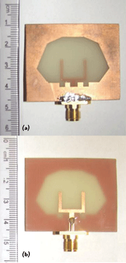
Figure 2 Photographs of the fabricated prototype: (a) front and (b) back.
Two small notches, denoted by A and C, respectively, with equal dimensions of S1 x S2, and another notch (B) between them, with dimensions of S1 x S3, are embedded at the bottom edge of the slot in order to generate the additional resonant frequencies and hence improve the total bandwidth and also finely tune the impedance matching characteristic. In this proposed design, the antenna is printed on both sides of an FR4 substrate with dimensions of 35 x 46 mm, thickness of 1.6 mm, relative permittivity εr = 4.4 and loss tangent = 0.02. The microstrip feed line of the antenna, with a width of 2 mm, is designed for a 50 Ω impedance and terminated with a standard SMA connector so that it can be connected directly to a measurement system or other standard microwave modules, as shown in Figure 2. All the simulations have been carried out using a finite element method (FEM) software "Ansoft High-Frequency Structure Simulator" HFSS 10.12
Parametric Study and Discussion
The proposed modified octagonal wide-slot antenna without any notches (A, B and C) is considered. In this design, the sizes of the sides of the slot and the dimensions of the fork-like tuning stub are the important parameters that affect the existence and positions of the resonant frequencies and hence the total bandwidth and impedance matching. The optimized values of all sides of this slot, which are not equal to each other, are shown in the figure. Another important parameter (in the feeding structure) to be considered is the distance between two arms of the fork-like stub, df. In this study, the other dimensions of the tuning stub, especially the length of the two arms (= 9.7 mm), are fixed.
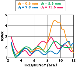
Figure 3 VSWR characteristics for different values of df.
Figure 3 shows the full wave VSWR simulation results of this proposed octagonal wide-slot antenna for different values of df. From this figure, it is clear that a wide bandwidth with relatively good matching especially in the upper bands is achieved by tuning the distance between the two arms of the fork-like stub, df. Moreover, it is seen that by using this form of the octagonal wide slot, four resonances can be excited. By selecting df = 9.8 mm, a wide bandwidth from 2.55 to 10.25 GHz (120.3 percent) for a VSWR less than 2 is obtained. Also note that, by varying the length and width of the two arms of the fork-like stub, the matching is only slightly affected and the bandwidth is about the same. From the geometry of the proposed antenna, it is observed that the internal periphery of this octagonal slot is equal to 92.6 mm (= 10 + (2 x 7.6) + (2 x 13.1) + (2 x 8.6) + 24 mm). This effective length is almost equivalent to 1.05λg, where λg corresponds to the first resonant frequency at 3.4 GHz, for df = 9.8 mm. This result shows that the performances of this proposed wide-slot antenna and a magnetic λ/2 dipole are similar.
In this section, the effects of the three notches (A, B and C), embedded at the bottom edge of the octagonal wide slot on the total bandwidth and impedance matching, are investigated. Also note that these notches are placed below the microstrip-fed line. Therefore, they have a strong effect on the input impedance of the antenna (and hence the impedance matching). From previous discussions, it seems that the important effect of these notches is to generate additional resonances. As a result, by properly adjusting the positions and dimensions of these three notches, with small electrical sizes with respect to the first resonance, at the bottom edge of the slot, new additional resonant frequencies are generated at the higher end of the UWB range, and hence the total bandwidth is increased. Moreover, a very good impedance matching over the whole bandwidth is obtained.

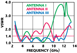
Figure 4 Simulated VSWR characteristics with different number of notches.
The VSWR characteristics of the proposed modified octagonal wide-slot antenna with different numbers of notches for three various cases (three antennas: I, II and III) listed in Table 1, are shown in Figure 4. The positions of the three proposed notches are shown in the antenna geometry and their optimized dimensions are: S1 = 2 mm, S2 = 3 mm and S3 = 4 mm. Comparing the three antennas (I, II, and III) shows that by using the three notches (A, B and C) simultaneously, a wide bandwidth with very good impedance matching can be achieved. Antenna III shows a simulated wide bandwidth from 2.5 to 12.8 GHz (134.6 percent) for a VSWR less than 2. By employing the three notches simultaneously, a very good impedance matching from 3.2 to 12.3 GHz (117.4 percent) for a VSWR less than 1.4 is also obtained. Therefore, this proposed structure of the wide-slot antenna is very suitable for UWB applications because of its small size, wide bandwidth and very good impedance matching. It is also noted that two new resonances at 11 and 12 GHz are generated, only because of using the three notches at the bottom edge of the slot. Although it is not shown here, it was found that by increasing S3 (in Antenna I) or S2 (in Antenna II), the upper edge of the frequency band is decreased. The performances of S1, S2 and S3 are similar.
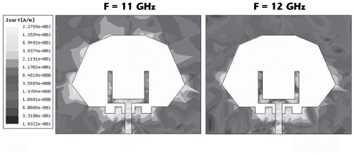
Figure 5 Surface current distribution for antenna III.
The simulated current distributions of the proposed octagonal-like wide-slot antenna at the two new resonances of the three notches (A, B & C), 11 and 12 GHz, are shown in Figure 5. On the ground plane, the current is mainly distributed along the edge of the slot for all of the two different frequencies. More current distributions can be seen around the three notches than in any other areas of the ground plane, which implies that these notches resonate at 11 and 12 GHz.
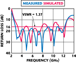
Figure 6 Simulated and measured return loss of the optimized wide-slot antenna.
Experimental Results
Based on the optimized parameters of the proposed antenna (Antenna III in Table 1), a prototype antenna was fabricated on a FR4 substrate with dimensions of 35 x 44 x 1.6 mm. The impedance bandwidth was measured using an Agilent 8722ES Vector Network Analyzer, and is shown in Figure 6, with good agreement between the simulated and measured results. The small difference between the positions of the resonances may be caused by the soldering effect of the SMA connector and its mechanical tolerance, which have been neglected in the simulations. It can be seen that the measured bandwidth defined by a VSWR less than 2 is from 2.5 to 12.8 GHz and for a VSWR less than 1.37 is from 2.8 to 12.2 GHz. It must be noted that the good performance of this type of printed wide-slot antenna is obtained while the volume of the antenna is approximately 2.46 cm3, which is smaller than similar wide-slot antennas previously reported.1-7
The measured radiation patterns (E- and H-planes) of the proposed wide-slot antenna (Antenna III) are shown in Figure 7. Within its impedance bandwidth from 3 to 10 GHz, the H-plane radiation patterns are almost omni-directional with relatively low cross-polarization level. From an overall view of these radiation patterns, the antenna behavior is quite similar to a typical printed wide-slot antenna.
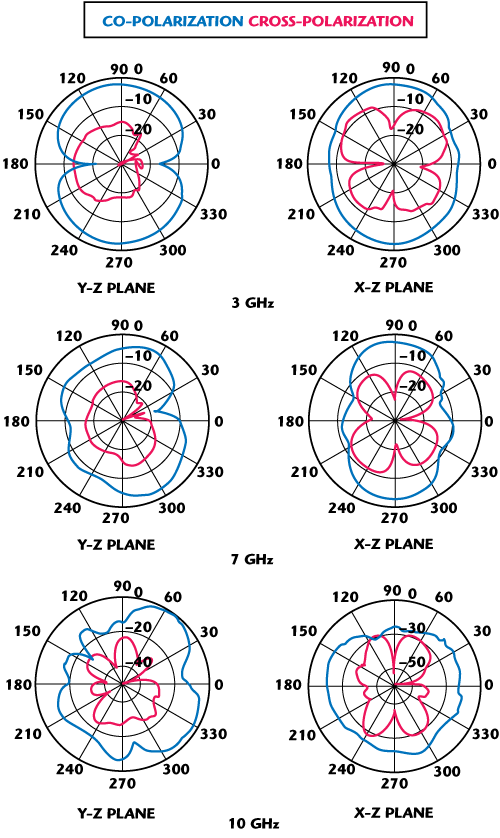
Figure 7 Measured radiation patterns.
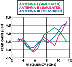
Figure 8 Measured and simulated gains of the three antennas.
The measured and simulated peak gains of the three antennas (I, II and III), from 3 to 11.6 GHz, are shown in Figure 8. It is seen that the measured and simulated gains fluctuate within the range from 2.75 to 4.9 dBi and reach their maximum values at 11.6 GHz for the two wide-slot antennas (II and III). The measured antenna gain variation for antenna III is observed to be less than 1.8 dBi, with a peak antenna gain of approximately 4.7 dBi.
Conclusion
A novel modified polygon-like wide-slot antenna with small size and fed by a 50 Ω microstrip line has been presented and investigated. Experimental results show that the impedance bandwidth of an octagonal-like slot antenna can be significantly improved by using three small, optimized notches at the bottom edge of the slot. Moreover, by using these three notches at the periphery of the slot and optimizing the octagonal-shaped slot and the fork-like stub dimensions, a very good impedance matching over the whole bandwidth, from 2.8 to 12.2 GHz (125.3 percent) for a VSWR less than 1.37, has been obtained. However, the measured total bandwidth of the fabricated antenna, determined by a 10 dB return loss, is equal to 10.3 GHz, from 2.5 to 12.8 GHz. Within this wide impedance bandwidth, the gain variation is less than 1.8 dBi. These good characteristics, with the compact dimensions of 35 x 44 mm for the proposed wide-slot antenna, make it attractive for future UWB applications.
Acknowledgment
The authors thank the Iran Telecommunication Research Center (ITRC) for its financial support and its Antenna & Microwave Laboratory, where the proposed antenna was tested.
References
- P. Li, J. Liang and X. Chen, "Study of Printed Elliptical/Circular Slot Antennas for Ultra-wideband Applications," IEEE Transactions on Antennas and Propagation, Vol. 54, No. 6, June 2006, pp. 1670-1675.
- J.Y. Jan and J.C. Kao, "Novel Printed Wideband Rhombus-like Slot Antenna with an Offset Microstrip-fed Line," IEEE Antennas Wireless Propagation Letters, Vol. 6, 2007, pp. 249-251.
- N. Behdad and K. Sarabandi, "A Wideband Slot Antenna Design Employing a Fictitious Short Circuit Concept," IEEE Transactions on Antennas and Propagation, Vol. 53, No. 1, January 2005, pp. 475-482.
- W.S. Chen and K.Y. Ku, "Broadband Design of the Non-symmetric Ground /4 Open Slot Antenna with Small Size," 2006 IEEE Antennas and Propagation Society International Symposium Digest, pp. 2563-2566.
- M. Kahrizi, T.K. Sarkar and Z.A. Maricevic, "Analysis of a Wide Radiating Slot in the Ground Plane of a Microstrip Line," IEEE Transactions on Microwave Theory and Techniques, Vol. 41, No. 1, January 1993, pp. 29-37.
- J.Y. Sze and K.L. Wong, "Bandwidth Enhancement of a Microstrip-line-fed Printed Wide-slot Antenna," IEEE Transactions on Antennas and Propagation, Vol. 49, No. 7, July 2001, pp. 1020-1024.
- W.S. Chen and F.M. Hsieh, "A Broadband Design for a Printed Isosceles Triangular Slot Antenna for Wireless Communications," Microwave Journal, Vol. 48, No. 7, July 2005, pp. 98-112.
- W.S. Chen and B.H. Kao, "A Triple-band Polygonal Slot Antenna for WiMAX Applications," Microwave Journal, Vol. 50, No. 1, January 2007, pp. 134-142.
- S. Sadat, M. Fardis, F. Geran, G. Dadashzadeh, N. Hojjat and M. Roshandel, "A Compact Microstrip Square-ring Slot Antenna for UWB Applications," 2006 IEEE Antennas and Propagation Society International Symposium Digest, pp. 4629-4632.
- W.J. Lui, C.H. Cheng and H.B. Zhu, "Improved Frequency Notched Ultra-wideband Slot Antenna Using a Square Ring Resonator," IEEE Transactions on Antennas and Propagation, Vol. 55, No. 9, September 2007, pp. 2445-2450.
- J.Y. Jan and J.W. Su, "Bandwidth Enhancement of a Printed Wide-slot Antenna with a Rotated Slot," IEEE Transactions on Antennas and Propagation, Vol. 53, No. 6, June 2005, pp. 2111-2114.
- High Frequency Structure Simulator (HFSS), Version 10, Ansoft Corp., 2005.
Majid Razavi-Rad received his BS degree in physics from Buali Sina University, Hamedan, Iran, in 1990. He is currently working toward his MS degree in electrical and telecommunications engineering at Urmia University, Urmia, Iran. His current research interests include UWB antennas and numerical methods in electromagnetics.
Changiz Ghobadi received his BSc degree in electrical engineering-electronics and his MS degree in electrical engineering-telecommunications from the Isfahan University of Technology, Isfahan, Iran, and his PhD degree in electrical-telecommunications from the University of Bath, Bath, UK, in 1998. He is currently an associate professor in the department of electrical engineering at Urmia University, Urmia, Iran. His primary research interests include antenna design, radar and adaptive filters.
Javad Nourinia received his BSc degree in electrical and electronic engineering from the Shiraz University, his MS degree in electrical and telecommunication engineering from the Iran University of Science and Technology and his PhD degree in electrical and telecommunications from the University of Science and Technology, Teheran, Iran, in 2000. He is currently an associate professor in the department of electrical engineering at Urmia University, Urmia, Iran. His primary research interests include antenna design, numerical methods in electromagnetism, microwave circuits, filters and signal processing.
Reza Zaker received his BSc degree in electrical and electronic engineering from Azad University, Tabriz, Iran, and his MSc degree in electrical and telecommunication engineering from Urmia University, Urmia, Iran, in 2008. His current research interests include printed, ultra-wideband (UWB) antenna design and bandwidth enhancement and miniaturization techniques, mobile small antennas, RFID, microstrip filters and numerical methods in electromagnetics.