
Modern mobile systems impose strict requirements for bandpass filters, such as small size, high selectivity, wide upper stopband, low insertion loss and cost. A planar microstrip elliptic-function BPF is a good choice for this purpose. BPF advances on the base of circular, square and triangular patch/ring resonators have been reported widely. For example, Hong proposed an elliptic-function BPF using meander square resonators for size reduction,1 while Zhang presented another elliptic-function BPF with capacitive loading for compactness and sharp rejection performances.2
Recently, there has been a growing interest in planar hexagonal resonators/filters because of their small size and high electric coupling. For instance, a compact BPF using hexagonal resonators was presented by Zhu.3 By adopting a skew-symmetric feed structure, an additional transmission zero occurs within the upper stopband of this filter, which generates a wide bandstop performance. In 2002, Chang provided a high-selectivity quasi-elliptic BPF with five hexagonal resonators,4 which proved that some frequency responses can be achieved by a fewer number of hexagonal resonators than with square resonators. Also, Mao described a dual-mode BPF using hexagonal resonators in 2006.5 The filter is easy to fabricate and possesses enhanced power-handling capability. However, the circuit sizes are large and occupy at least 0.83λg × 0.71λg, where g is the guided wavelength at the center frequency of the passband. To make the circuit size compact and enhance the coupling between resonators, Ni reported a hexagonal filter with a source-load coupling structure.6 The filter requires a size amounting to 0.32λg × 0.21λg.
In this article, a novel and small elliptic-function hexagonal BPF is proposed. The design techniques, etching slot and adding open stubs are analyzed and verified by simulations and measurements. Also, an asymmetrical 50 Ω feed structure is used. Compared to the reported hexagonal filters in the literature, the proposed filter exhibits size reduction and excellent transmission performances.
Hexagonal Filter Design and Circuit Modeling

Figure 1 Conventional hexagonal filter.

Figure 2 Type I hexagonal filter.

Figure 3 Type II hexagonal filter (dimensions in mm).
A conventional BPF design, using λ/2 hexagonal open-loop resonators, is shown in Figure 1. The filter electric coupling structure is chosen and elliptical frequency responses are achieved by using two skew-symmetric transmission line feeding structures.7,8 Based on the conventional filter, two pairs of inner open stubs and a pair of outer open stubs are added to produce the Type I filter shown in Figure 2. The inner open stubs increase the resonator’s self-capacitance, while the outer open stubs enhance the electric coupling between resonators. Based on the Type I filter, slots are etched in the resonator and the Type II is produced, as shown in Figure 3, where the dimensions are in mm. After etching one slot on each resonator, extra transmission zeros may occur. Additionally, the extra transmission zero can be adjusted by changing the slot’s length which leads to a wider stopband than before.9 Without occupying extra size, the proposed filter, with reduced center frequency and low insertion loss performances in the passband, may be realized.

Figure 4 Circuit model of the conventional hexagonal filter.
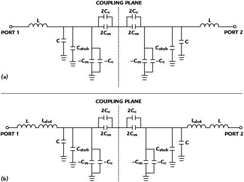
Figure 5 Circuit models of the Type I (a) and Type II (b) hexagonal filters.
According to the equivalent circuit model described by Hong,7 the circuits’ modeling of the hexagonal filters are implemented. Similar to the circuit model of the square open-loop resonator, the circuit model of the conventional hexagonal filter is set up and shown in Figure 4. L and C are the self-inductance and self-capacitance of the hexagonal open-loop resonator and Cm denotes the mutual capacitance. Correspondingly, the circuit models of the Type I and Type II hexagonal filters are given in Figure 5. The effects of the capacitive coupling from the inner open stubs and the outer open stubs are represented by Cc and Cstub, respectively. Furthermore, the self-inductance of the hexagonal open-loop resonator is improved by etching the slot. The increment is described by Lslot.
Results and Discussion

Figure 6 Insertion loss performance of the hexagonal filters.
To demonstrate the proposed topology usefulness, the filters were simulated with Ansoft HFSS 8.0; their insertion loss performance is presented in Figure 6. The substrate used for simulation and measurements is FR-4, 0.8 mm thick with a dielectric constant εr = 4.5. The input and output lines are 50 Ω microstrip lines. The physical dimensions of the filters have been given previously. From the comparison between the insertion loss of the conventional and proposed filters, it is found that the center frequency in the passband is decreased from 2.5 GHz to 1.8 Hz and the insertion loss in passband reduced from 4.2 to 1.1 dB. The center frequency and insertion loss are reduced by 28 percent and 3.1 dB, respectively. It shows that the outer open stubs increase the capacitive coupling between the resonators so that the insertion loss decreases. On the other hand, the total capacitive effect from the inner and outer open stubs increases so that the resonant frequency of the hexagonal resonator is reduced. Notice that there is an additional transmission zero in the upper stopband, which is located at 3.1 GHz for Type II. That is to say an improved wide stopband performance is obtained.
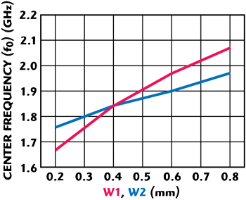
Figure 7 Center frequency of the proposed filter vs. W1 and W2 dimensions.

Figure 8 Location of the extra zero vs. S.
The relationship between the physical parameters, W1 and W2, and the center frequency is described in Figure 7. It is clear that the center frequency decreases when W1 (W2) becomes smaller. Also, the design parameter S is affecting the extra transmission zero location, as shown in Figure 8.

Figure 9 Proposed filter photograph.

Figure 10 Measured data for proposed filter.
The proposed Type II filter was fabricated and its photograph is shown in Figure 9. Its physical parameters are the same as shown previously, with W1 = 0.4 mm, W2 = 0.4 mm and S = 0.6 mm. The measured results are given in Figure 10. The measurements verify that the proposed filter has a fractional bandwidth of 23 percent with a center frequency of 1.84 GHz. The filter has a return loss greater than 15 dB from 1.71 to 1.98 GHz. The insertion loss in the passband is less than 1.5 dB. There are two transmission zeros on both sides of the passband. They are -41 and -38 dB at 1.35 and 2.37 GHz, respectively. Another transmission zero is -51 dB at 3.20 GHz. There is a good agreement between simulated and measured results. The circuit size is 21.2 × 12 mm. A comparative study of the sizes of the reported hexagonal BPFs6 (0.32λg × 0.21λg) and the proposed filter (0.24λg × 0.14λg) shows that the latter is more compact and its size is reduced by approximately 50 percent. The measurements were carried out on an Agilent 8722 vector network analyzer.
Conclusion
A novel design of a hexagonal BPF is introduced in this article. The techniques, etching slot and adding open stubs are applied to enhance the self-inductance and self-capacitance of the hexagonal open-loop resonators so that a compact filter with low insertion loss is achieved. Also, an extra transmission zero occurs, which leads to a wide upper rejection performance. Finally, this filter was designed, fabricated and measured. This compact BPF, with good transmission performance, has a potential for compact microwave circuit applications.
Acknowledgments
This work was supported by the 100 Talents Program of The Chinese Academy of Sciences in 2008.
References
1. J.S. Hong and M.J. Lancaster, “Compact Microwave Elliptic Function Filter Using Novel Microstrip Meander Open-loop Resonators,” Electronics Letters, Vol. 32, No. 6, 14 March 1996, pp. 563-564.
2. X.Y. Zhang, J.X. Chen and Q. Xue, “Compact Bandpass Filter Using Open-loop Resonators with Capacitive Loading,” Microwave and Optical Technology Letters, Vol. 49, No. 1, January 2007, pp. 83-84.
3. Y.Z. Zhu and Y.J. Xie, “New /2 Microstrip Bandpass Filters Using Skew-symmetric Feed Structure,” Microwave and Optical.Technology Letters, Vol. 50, No. 2, February 2008, pp. 440-442.
4. K.F. Chang, K.W. Tam, W.W. Choi and R.P. Martins, “Novel Quasi-elliptic Microstrip Filter Configuration Using Hexagonal Open-loop Resonators,” 2002 IEEE International Symposium on Circuits and Systems Digest, Vol. 3, pp. 863-866.
5. R.J. Mao and X.H. Tang, “Novel Dual-mode Bandpass Filters Using Hexagonal Loop Resonators,” IEEE Transactions on Microwave Theory and Techniques, Vol. 54, No. 9, September 2006, pp. 3526-3533.
6. D. Ni, Y. Zhu and Y. Xie, “Design of Hexagonal Filter with Source-load,” Electronics Letters, Vol. 42, No. 23, 9 November 2006, pp. 1355-1357.
7. J.S. Hong and M.J. Lancaster, “Couplings of Microstrip Square Open-loop Resonators for Cross-coupled Planar Microwave Filters,” IEEE Transactions on Microwave Theory and Techniques, Vol. 44, No. 11, November 1996, pp. 2099-2109.
8. C.M. Tsai, S.Y. Lee and C.C. Tsai, “Performance of a Planar Filter Using a 0 Feed Structure,” IEEE Transactions on Microwave Theory and Techniques, Vol. 50, No. 10, October 2002, pp. 2362-2367.
9. C.F. Chen, T.Y. Huang and R.B. Wu, “Miniaturized Microstrip Quasi-elliptical Bandpass Filters Using Slotted Resonator,” 2006 IEEE MTT-S International Microwave Symposium Digest, pp. 1185-1188.