
 All companies need to see increasing income year on year to please investors and to fund their growth. A mounting need for microwave design, combined with skilled worker shortages, make seamless growth challenging. As a result, engineers in rapidly growing companies are faced with increased workloads, more diverse work and the requirement to work with other, perhaps unfamiliar parts of the company to achieve design goals.
To make growth easier to manage, seamless workflow between software design tools has become critical. For example, different departments in a company, which may be geographically separated, could be designing handset antennas, PCB layout, antenna drive circuits and interconnects. They may all need to communicate layout, circuit and EM data and, due to mergers, they may all have different tool vendors. So, how does a company ensure that an overstretched engineer does not have to redesign the wheel every time he works on a new or updated design?
CST has addressed these issues. Traditionally the company has supplied point tools for full wave microwave/RF design and optimization, but in recent years it has made its products fit centrally into the much wider design flow to address current requirements. Thus, the newly released CST STUDIO SUITE™ version 2008, incorporating CST MICROWAVE STUDIO® (CST MWS), is the most open and easily integrated tool ever released by the company.
Its customer centric approach is designed to focus on the company’s core 3D EM specialization and provide easy workflow to other ‘best in class’ tools. The following reveals how the suite has become not only a central part of the overall design process, but also a powerful tool with its own well defined internal workflow for solving multiple applications with the best turnaround times possible.
External Workflow
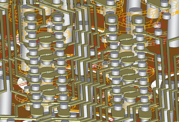
Figure 1 shows a typical workflow situation. Inputs may come from layout tools such as those supplied by Cadence (see Figure 2) or new in version 2008, Mentor Graphics. It may come from planar EM simulators such as Momentum or Sonnet or it may be in an interchange format like ODB++ or multilayer Gerber. Virtually all other mechanical formats are supported and, new to this version, other 3D EM formats are accepted.
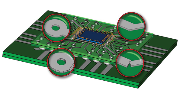
Poor mechanical geometry and fault intolerant meshing have plagued the workflow in this sector for many years, causing frustration and delay at the first hurdle. Import healing and fault tolerant meshing have been big areas of research for CST and in the vast majority of cases, complex geometries are effectively healed and meshed without user input. Figure 3 shows the typical automatic healing process on import. The facets are removed on the pad and the trace is joined correctly.
Input may also come from the output of another EM tool. For example, new in version 2008 is the capability to import near field data from Sigrity’s Speed2000 or PowerSI tools. This means that a highly complex PCB stack-up can be simulated in Sigrity’s tool and the surrounding near field data exported to CST MWS. At this point radiation, coupling or proximity simulations can be carried out. A similar link is included to Simlab’s PCBmod tool, based on surface currents.
As well as importing layouts from external planar/circuit simulators, CST MWS allows co-simulation and co-optimization with circuit tools from AWR and Agilent. This essentially means that a block appears in the circuit schematic, greatly simplifying circuit/EM co-design. Workflow has also been improved to the closely coupled circuit tool CST DESIGN STUDIO™, with a new layout viewer and editor as well as tuning bars, time domain simulation, eye diagram tools and IBIS import.
On the output side, the company has always been strong in post-processing of data with clear and intuitive visualization and post-processing templates allowing automated dataset manipulation. Some new features in version 2008 are HSPICE creation, far field sub-ranges, near field sub-volumes and Smith chart table creation.
Internal Workflow
With increasingly diverse product lines and new requirements for EM characterization due to higher signal speeds, higher component densities and miniaturization, the need has arisen for more than one solver to address the vast range of 3D microwave/RF applications. This is because no one solver can solve all applications efficiently and in some cases, a solver will fail on an application entirely. As the solver choice can make significant differences in run time, it becomes essential to offer the choice to speed up overall workflow. Thus, version 8 offers a choice of solver to suit the application, while keeping a unified and class leading interface so that the solver selection is a push of one button.
The CST MWS time domain solver is improved in version 2008 and is a consolidation of major improvements made over the last couple of years. As will be described later, hardware acceleration has been introduced. The time domain solver is highly suited to very complex, multiband/broadband structures and is the most general-purpose solver in the suite.
The newer frequency domain solver achieves a high level of performance. For example, frequency domain solvers work by solving single frequency points and for broadband applications they have to solve many samples in order to build up an accurate response. Distribution of those frequency samples to multiple computers is now possible to give a much faster overall solve time. Frequency domain analyses can be done with either direct or indirect methods. CST MWS has both, and exhibits good speed and memory usage.
In particular the indirect solver has low memory usage for large models. The direct solver, which has advantages for smaller multiport structures, is now 20 percent faster with a 50 percent memory usage reduction over version 2006B. The frequency domain solver allows repeating unit cells to be created and these offer far field and RCS calculation based on Floquet modes. In general the frequency domain solver is well suited to phased-array design, electrically small and very narrow band devices.
Other solvers available include a fast resonant solver for high Q cavity filter design and a new integral equation solver for electrically very large structures such as airplanes or ships. Improvements to the integral solver in version 2008 include the ability to use a far field source to excite the structure and the implementation of lossy metals.
A thermal solver adds to the internal workflow within version 2008. Besides the thermal analysis of electromagnetic losses (dielectric and conductive) from CST MWS simulations, the deposed particle energy derived from CST PARTICLE STUDIO™ can be used as a heat source.
Hardware Acceleration
It is accepted that graphics cards (GPU) are significantly faster than CPUs when it comes to rendering extremely large numbers of pixels. What is not so well known is that the same technology can be applied to solve numerical problems to give an order of magnitude speed-up. CST has been working with Acceleware to bring this technology to CST MWS and it is now available in version 2008.
One of the key advances is that the method retains all the accuracy and mesh size reduction that arise from the use of the conformal Perfect Boundary Approximation (PBA).® The use of a GPU with this technique additionally gives a large speed injection to the most complex industry simulation problems. In other words, the bigger the problem, the greater the speed-up that is achieved.
This GPU hardware acceleration is available either as a PCIe card for the desktop or as a ‘cluster in box’ comprising two external cards, which bring capacity and speed benefits to those who may have thought their problems were simply too difficult for 3D analysis.
The company has also been working directly with Intel in high performance computing to optimize code performance on the latest generation of multicore Intel processors easily achieving a 200 percent + speed increase against previous generation processors.
Modeler Improvements
Some very useful additions to the main modeling interface have been added to version 2008 to further improve workflow. Windows Vista is fully supported (see Figure 4), as is Linux RedHat Enterprise, both on 32- or 64-bit platforms. A project management tool has been added to allow for easier file management and exchange of data.
This includes copy/paste of structure parts either within the same project or to other projects, import of CST DS layouts and sub models, thus allowing the creation of library components. Also, for maintained licenses and those connected to the Internet, automatic updates can be enabled ensuring the latest version is always on hand. As usual all update details are shown in the Help – history of changes menu.
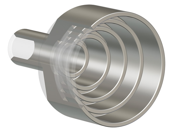
An artistic improvement, but nevertheless one that allows quick recognition of materials, is the addition of true reflective materials. A graphic is reflected in the metal to give the real appearance of a shiny metal (see Figure 5). Other improvements to speed up workflow include arbitrary pick-points on surfaces and an update to the ACIS modeling kernel.
Conclusion
For version 2008 of CST STUDIO SUITE, external and internal workflow improvements have been the key focus. With easy data exchange to and from other software tools, a choice of first class solvers and a range of modeler usability improvements, the engineer is able to leverage the latest developments in 3D electromagnetics to bring designs to market faster and with lower risk.
CST of America
Framingham, MA
(508) 665-4400
www.cst.com
RS No. 300