
The testing process for radar systems is crucial to their reliable operation and verification, ensuring peak performance when deployed in the field. Stringent testing is essential for the operational effectiveness of radar systems in the most challenging conditions and for their consistency during long periods of bad weather and instances of interference and jamming. Radar systems are often deployed in conflict zones or mission-critical situations (see Figure 1) and therefore, testing can highlight weaknesses in the system, allowing them to be rectified and redundancy incorporated.
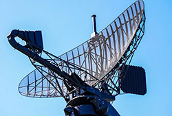
Fig 1. Military radar air surveillance on a ship.
Testing also validates the system’s performance, ensuring that it meets technical specifications such as detection range, resolution, tracking accuracy and measurement speed. All of these aspects are critical for detecting stealth targets. Testing early in the development process also enables the identification of any design flaws. By using hardware-in-the-loop simulations, these flaws can be rectified early in the process. Additionally, testing for regulatory compliance and safety reasons ensures its safe operation. Any cybersecurity issues, which are increasingly important, can be picked up at this stage. Testing also allows engineers to evaluate how the system performs within networks from a compatibility and interoperability standpoint.
COMPACT TEST RANGES
Compact test ranges (CRs) are widely used to carry out essential testing on radar systems and operate across a range of frequency bands. They are highly convenient because they simulate far-field radar conditions in a small, controlled environment often using a parabolic reflector. They measure radar cross-section (RCS) and antenna performance of the radar system.
Far-field simulation creates plane waves, a type of wave where the crests and troughs form flat, parallel planes rather than expanding curves, all traveling in the same direction. Think of it as a perfectly straight, wide wave moving forward, often used to approximate light or sound coming from a very distant source.
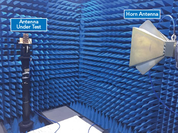
Fig 2. Anechoic chamber with horn test antenna.
The CR consists of an anechoic chamber, a feed horn, (see Figure 2) and a parabolic antenna that generates the test plane wave, a constant frequency wave that propagates in a single direction with uniform intensity.
THE QUIET ZONE
The quiet zone (QZ) in a CR is a central area where a reflector converts spherical waves into a high-quality uniform plane wave and simulates far-field conditions in a confined space. The QZ is identifiable by its low-level phase ripples and low cross-polarization. The size of the QZ can vary from small to very large, depending on the reflector size and design.
The location of the feed horn is integral, as this is used to generate the wide-beam illumination of the reflector.
THE FEED HORN SYSTEM
A feed horn is suitable for use in high frequency ranges, and it works in a similar way to a hunting horn or a woodwind instrument. Essentially, the horn is a flared waveguide used as a separate antenna or as a radiator to feed a reflector antenna, such as a parabolic antenna. Feed horns provide moderate to high gain and low return loss across a very wide bandwidth and are used for microwave and mmWave bands.
There are several types of feed horns, but the most commonly used in radar testing is a corrugated type. These feature parallel grooves on the inside surface of the horn. They offer a wider bandwidth with smaller sidelobes and cross-polarization. The sidelobes produced are low and the corrugated horn also produces symmetric beam patterns, which are important for minimizing false targets and improving target accuracy. Feed horns offer stable performance over a wide bandwidth and therefore a single horn can be used to test across many frequency bands.
Corrugated horns are more expensive to produce than standard horns, but they do offer another level of performance from the perspective of cross-polarization and beam shaping.
DRAWBACKS
The CR’s capability can be limited by the feed antenna. For antennas with fixed aperture distributions, achieving high frequency bandwidth and constant illumination is challenging due to reflector surface accuracy, edge diffraction, feed horn design, signal instability, environmental sensitivity and maintaining polarization purity. Several banded feeds must be mechanically sequenced in the measurements.
The limitations of the feed horns increase operational costs for low-observable measurements. Feed horns can achieve high bandwidth but often do not deliver the constant illumination required in the CR.
Today, the exploration of focal plane arrays (FPAs) is emerging. FPAs can be used to resolve these issues, increase instantaneous bandwidth and measurement quality and reduce operational costs.