
Due to their reciprocal nature, passive antennas can be completely characterized in transmit or receive mode. This is in contrast with active antennas where characterization is performed in one of two modes, with the other deemed not suitable due to non-reciprocity. This requires an antenna measurement facility be able to perform measurements in both transmit and receive modes. This article describes a measurement setup used to characterize an active radar module (ARM) in transmit mode and presents the results of these measurements, which were performed in the compact antenna test range at the Institute of High-Frequency Technology at the University of Aachen (RWTH), Aachen, Germany.
Active antennas have been attracting more interest for mobile communications (e.g., base stations) due to their flexibility and efficiency.1 In contrast with passive antennas, the measurement of active antennas is more challenging. The term active antenna comes from the fact that active elements, such as transmitter power amplifiers (PA) and receiver low noise amplifiers (LNA), are part of the antenna. These active elements restrict antenna operation to either transmit or receive; thus, an active antenna must be characterized for either one or the other. Some active antennas are supplied with (so called) transmit/receive modules (Tx/Rx) to enable operation in both modes.2 In this case, each mode is characterized separately.
Difficulties associated with active antenna measurements can depend upon several factors. First is the antenna type. It is particularly challenging to characterize antenna arrays that, apart from simply measuring the radiation pattern, need calibration.3-5 Second is the measurement facility. This is challenging especially for spherical near-field measurement facilities that require accurate phase and amplitude information to perform the near-to-far field transformation.6 Third is the mode of operation (i.e., transmit or receive). Last is the availability of phase information. This is the case for applications where an entire system, including the Tx and Rx antennas, digital signal processing (DSP) modules, amplifiers and other components, are integrated onto a single chip, making access to phase information very difficult, or impossible, unless taken into account in the early design stages.
This article presents the results of measurements run in the compact antenna test range (CATR) at the Institute of High Frequency Technology (IHF) in Aachen, Germany.7 The device under test (DUT) is a prototype active radar module developed by Anristu®.
Active Radar Module
The ARM is a stepped-frequency, continuous-wave (SFCW) radar. It consists of two beam-steerable dual-waveguide-fed horns, one used for transmission of CW signals, and the other for receiving signal reflections. The horns interface with nonlinear-transmission-line-based (NLTL) variable phase shifters,8 samplers, frequency multipliers and supporting circuitry, resulting in a compact assembly that is controlled from a USB interface. It operates from 55 to 65 GHz. Figure 1a is a top view showing the Tx and Rx horn antennas. Figure 1b is a bottom view showing the printed circuit board, DC-power and USB connectors.

Figure 1a Photo of the Anritsu active radar module (ARM); top view (a).
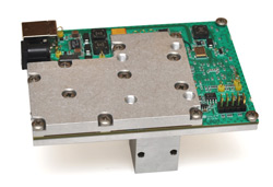
Figure 1b Photo of the Anritsu active radar module (ARM); bottom view (b).
Figure 2 shows a block diagram of the SFCW ARM consisting of a sampling directional coupler and receiver, beam-steerable transmit and receive antennas, a CW stimulus source and USB control. The lower branch shows the antenna. One capability of SFCW radars is the measurement of distance from an object. This is done by sweeping the frequency of the CW transmitter over a given frequency range, measuring the reflection coefficient, and making use of a chirp-z transform to recover the roundtrip time delay from transmission to reception. The time delay determines the object’s distance relative to the radar.9,10 Another capability of this module is beam steering, achieved with the aid of variable phase shifters (VPS) integrated with a dual-waveguide-fed horn antenna. The introduction of a phase shift between the excitation signals enables main-beam steering, or scanning, by phasing one waveguide aperture with respect to the other. A 12 V power supply provides DC power, while module control and programming (e.g., setting the transmit frequency and phase shift necessary for main-beam scanning) are realized via a USB interface.
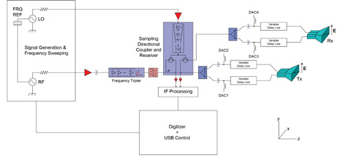
Figure 2 Block diagram of the NLTL-based SFCW radar module.
Measurement Facility
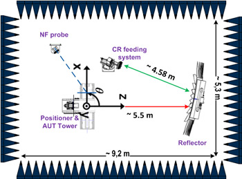
Figure 3 Schematic showing the combined compact antenna test range and spherical near field antenna measurement facility at the IHF in Aachen, Germany.
The module was measured in the CATR at the Institute of High Frequency Technology in Aachen (see Figure 3). This is a combined compact antenna test range and spherical near field antenna measurement facility (CATR/SNF) with a frequency measurement capability from 800 MHz to 75 GHz. The SNF is used from 800 MHz up to 12 GHz, while the CATR covers the frequency range from 2 to 75 GHz.
A CATR is often operated in the transmit mode (i.e., the feed system illuminates a reflector creating a quasi plane wave region called the quiet zone (QZ). The antenna under test (AUT) is situated in this region and its response to the stimulating field of the QZ is recorded. In this case, the AUT is characterized on receive. For the evaluation of this module, however, the CATR must also characterize the AUT in transmit.
Passivity of the system normally guarantees functionality, keeping in mind that the system is wavelength dependent.11,12 It is important to realize that in a CATR, however, in order to operate in the dual-mode with minimal error, the AUT must create a plane wave at the reflector’s surface that is, in turn, focused at the feed. The well-known criterion
r=2D2/λ (1)
where D is the maximum AUT size and λ is the operational wavelength, is a good approximation of the far field distance. This is the minimum separation between the AUT and the reflector required to ensure an approximate plane wave at the reflector’s surface.13 For the ARM, using the aperture plane of the horns as the phase center, this distance is 0.36 m at an operating frequency of 60 GHz. Given that the actual distance between the AUT positioner and the reflector is around 5.5 m, a plane wave condition at the reflector’s surface is ensured. For this measurement an MI-Technology standard gain horn (SGH) model (MI-12-40)14 is used as a receive feed.
The feed is connected to a Rohde & Schwarz two-port harmonic mixer. This mixer uses two parallel reverse-connected diodes, and requires no biasing.15 The receiver is a Rohde & Schwarz FSP 40 spectrum analyzer containing a diplexer to separate the LO and IF signals which are fed on the same cable. The cable is short to preserve dynamic range by reducing high frequency signal losses.
MATLAB® is used to control the measurement process. Using visual basic scripting offered by the Active Cell software, the positioner, for example, is easily controlled using MATLAB. The spectrum analyzer is triggered by the positioning system through the external triggering pin on its back panel (i.e., hardware triggering), ensuring correct sampling of the angular points.
Measurement Results
Figures 4 and 5 show two plots for the QZ field acquired in the dual-mode, i.e., the ARM is in the transmit mode and moving across the QZ while the MI-12-40 SGH acts as a receive feed horn in the focal plane of the reflector. The red curves represent the actual measured QZ field, while the blue curves represent the second degree curve fitting polynomial. These help determine amplitude ripple and taper of the fields in the QZ and are, in turn, indicators of QZ quality at that specific frequency.16
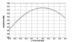
Figure 4 H-plane Quiet Zone scan at 55 GHz.
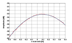
Figure 5 H-plane Quiet Zone scan at 57 GHz.
Several observations are worth noting. First, the ripple effect is small while the taper effect is large. This is expected since the feed used is directive and very small compared to the reflector’s size. Second, the amplitude difference between Figures 4 and 5 is due to the ARM, itself. Third, losses are mainly due to free-space and RF cable losses. The fourth and last observation is that there is a QZ center frequency shift, which is due to defocusing (i.e., defocusing from the optimum point, where the system is an offset-fed single reflector) of the feed that causes a reorientation (scanning) of the plane wave direction in the QZ. Figure 6 illustrates this effect based on geometrical optics. The defocusing angle of the feed would in this case be around 1° (sin-1 of 0.1 m divided by 5.5 m -- see Figures 3 and 4).
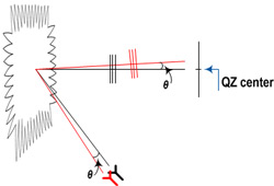
Figure 6 Schematic showing the effect of feed defocus.
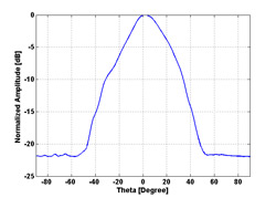
Figure 7 H-plane pattern of the ARM at 55 GHz for zero delay.
Figure 7 shows the H-plane pattern of the ARM at 55 GHz. This plot is taken for zero delay (i.e., both lines are fed in phase). The patterns are not symmetrical in shape, which indicates that the amplitudes of the excitation signals fed to the antenna are not equal, which is most likely due to asymmetry introduced during the assembly of the phase-shifter-to-horn transitions.
Figure 8 shows the pattern evolution at 55 GHz for a zero phase-shift voltage on line 1 and different phase-shift voltages on line 2. The figures show the scanning effect versus phase-shift voltage. For higher voltages, the ARM becomes insensitive as the phase shifter reaches saturation. To characterize the module from 60 to 65 GHz, an identical setup is used, employing an Anritsu signal analyzer (MS2830A)17 with an external two-port harmonic mixer.
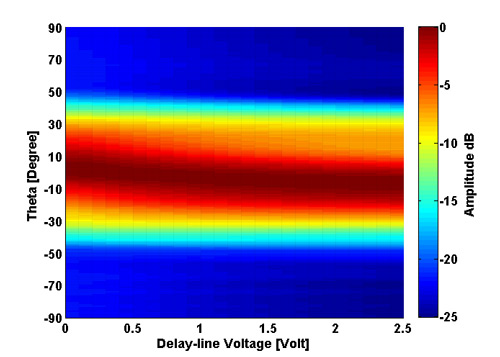
Figure 8 H-plane patterns of the ARM at 55 GHz versus phase shift voltage setting.
Conclusion
The process used to characterize a prototype active radar transmit module in a compact antenna test range is described. An active radar module, characterized over the frequency range of 55 to 65 GHz, is used to demonstrate measurements of pattern shaping and scanning depending on power and relative phase at its two apertures.
References
- "Active Antenna Systems - A Step-Change in Base Station Site Performance," Nokia Siemens Networks, 2012.
- S. Drabowitch, A. Papiernik, Hugh Griffiths, J. Encinas and B.L. Smith, Modern Antennas, 2nd edition, Springer, 2005.
- P. Knott, T. Bertuch, H. Wilden, O. Peters, A.R. Brenner and I. Walterscheid, "SAR Experiments Using a Conformal Antenna Array Radar Demonstrator," International Journal of Antennas and Propagation, Vol. 2012, No. 142542.
- T. Bertuch, P. Knott, H. Wilden and O. Peters, "Wide-Band Radar Front-End Calibration for Imaging SAR Experiments With Conformal Antenna Array," Proceedings of the 5th European Conference on Antennas and Propagation, April 2011, pp. 2610,2614.
- W. Haselwander, M. Uhlmann, S. Wustefeld and M. Bock, "Measurement on an Active Phased Array Antenna on a Near-Field Range and an Anechoic Far-Field Chamber," 31st European Microwave Conference, September 2001, pp. 1-5.
- J.E. Hansen, "Spherical Near-Field Antenna Measurements," Peter Peregrinus Ltd., London, UK, 1988.
- www.ihf.rwth-aachen.de
- K. Noujeim, J. Martens and T. Roberts, "White Paper - Frequency-Scalable Nonlinear-Transmission-Line-Based Vector Network Analyzers", Anritsu.
- E.F. Knott, J.F. Shaeffer and M.T. Tully, Radar Cross Section, 2nd edition, SciTech Publishing Inc. Raleigh, NC, 2004.
- M.I. Skolnik, Radar Handbook, 2nd edition, McGraw-Hill Inc., NY, 1990.
- H. Shakhtour, R. Cornelius and D. Heberling, “Three Antenna Gain Determination Method in Compact Antenna Test Ranges,” Loughborough Antennas and Propagation Conference, November 2013.
- S. Brumley, "Extending the Low-Frequency Limits of the Compact-Range Reflector," IEEE Antennas and Propagation Magazine, Vol. 38, No. 3, June 1996, pp.81-85.
- C.A. Balanis, Antenna Theory: Analysis and Design, 2nd edition, John Wiley & Sons, 1997.
- www.mitechnologies.com/images/catalog/Antenna%20Solutions/MI-212_Family_of_Standard_Gain_Horns.pdf, accessed on 3 December, 2013.
- “Harmonic Mixer, Operating Manual,” Rohde & Schwarz Test and Measurement Division.
- C.A. Balanis, Modern Antenna Engineering, John Wiley & Sons, 2008.
- “MS2830A Operating Manual,” www.anritsu.com/en-US/Products-Solutions/Products/MS2830A.aspx, accessed on 12 October 2013.
Hammam Shakhtour received his B.Sc. degree in electrical engineering from Birzeit University, Birzeit, Palestine, in 2005 and his M.Sc. degree in electrical engineering and information technologies from Karlsruhe Institute of Technology (KIT), Germany, in 2009. He is currently at the Institute of High Frequency Technology (IHF), Aachen, Germany working on near field measurement techniques for active antenna characterization as part of his Ph.D.
Dirk Heberling studied electrical engineering and graduated from RWTH Aachen in 1987. He was employed as a scientist at the Institute for RF-Technologies, RWTH Aachen from 1987 to 1993. He received his Ph.D. (Dr.-Ing.) in 1993 for his thesis on conformal microstrip antennas. In 1993, Heberling joined IMST GmbH, Kamp-Lintfort to establish a new Antenna Section, and from 1995 to 2003 he was head of the Antennas Department, which was reorganized into the Department of Antennas and EMC in 1998. From 2003 to 2008, he took over the Department of Information and Communication Systems of IMST. He moved to RWTH Aachen in 2008 where he is currently head of the Institute and holder of the chair for High Frequency Technology.
Karam Noujeim received his graduate electrical engineering degrees in Canada starting with a master of engineering from McGill University in 1990, and an M.A.Sc. and Ph.D. from the University of Toronto in 1994 and 1998. In 2001, he was a visiting academic researcher at the Picosecond Electronics Laboratory, University of California, Santa Barbara. He was involved with the development of CAD tools for assessing the susceptibility of printed-circuit boards to electromagnetic interference (Bell-Northern Research, Ottawa, Jan. 1990 – Sept. 1992), and with the design of millimeter-wave components for LMDS (A divestiture of the Watkins-Johnson Company, Aug. 1998 – June 1999). In June 1999, he joined the Microwave Measurements Division of Anritsu Co. (formerly known as Wiltron), in Morgan Hill, Calif., as a senior microwave design engineer. In this role, Noujeim designed millimeter-wave transmitters, receivers and antennas for automotive-radar testing; NLTL-based directional samplers, harmonic generators, frequency-extension modules and sub-systems for a wide variety of measurement instruments; and high-sensitivity micro-machined thermal power sensors. He is currently a fellow hardware engineer and leads the technology group of Anritsu-USA’s emerging business operations.
Ferdinand Gerhardes studied communication electronics with a focus on radar and navigation at University of Federal Armed Forces, Hamburg and finalized his Dipl.-Ing. Nachrichtentechnik in 1987. Until 1994 he served as an electronic warfare officer and entered industry at Fuba Hans Klobe & Co. For the last 20 years, Gerhardes has been engaged in the wireless industry, holding several marketing and sales positions.
Peter Knott received his Diplom-Ingenieur and Ph.D. degree from RWTH Aachen University, Germany, in 1994 and 2003. In 1994 he joined the Fraunhofer Institute for High Frequency Physics and Radar Techniques FHR (formerly FGAN e.V.) in Wachtberg, Germany. The focus of his work was design and development of antenna arrays and active antenna front ends as well as electromagnetic modelling and beamforming methods for conformal antenna arrays. Since 2005 Knott has been head of the Department Antenna Technology and Electromagnetic Modelling (AEM).