
Due to their physical construction (leads, internal structure, PCB traces), all electronic components, including surface mount capacitors, have unwanted parasitic characteristics that deviate from their ideal electrical behavior, especially at high frequencies where these parasitics create issues such as signal distortion, increased noise (crosstalk), reduced bandwidth, timing errors, power loss, and amplifier instability.
It is critical to incorporate these effects into circuit simulations with high-frequency models that accurately represent component parasitics so that the impact on system performance can be properly addressed during the design phase of any product development.
Recently (December 2025), Murata updated its capacitor and inductor equivalent circuit component library for Microwave Office with new part numbers. The components are parameterized to allow tuning and optimization for each part number, allowing designers to use component models with realistic frequency characteristics.
For example, comparing a Murata inductor model with the same constant (3.6 nH) and an ideal inductor model, we can see that there are differences between the two. This is because an actual inductor component has parasitics that change their performance from the ideal response. Taking these parasitic effects into account is necessary to ensure design success.
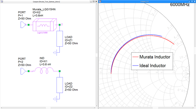
Figure 1. RF response of a Murata SMD Inductor (shorted to ground) vs an ideal inductor shows the impact of parasitics on high-frequency performance.
There are also differences between ideal and actual component models for capacitors. In addition to capacitance, real components have parasitic components such as equivalent series inductance (ESL), which also affects impedance at high frequencies. When L and C components are combined in a network, the differences due to parasitic effects become even more pronounced, causing significant changes in characteristics. Taking these parasitic effects into account improves design accuracy and the reliability of simulations.
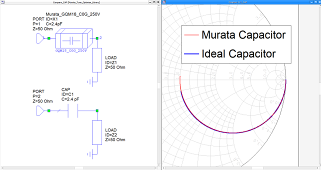
Figure 2. RF response of a Murata SMD Capacitor (shorted to ground) vs an ideal capacitor shows the impact of parasitics on high-frequency performance.
Murata's library for Microwave Office not only provides circuit analysis models, but also 2D and 3D component information. You can also create layouts by combining wiring.
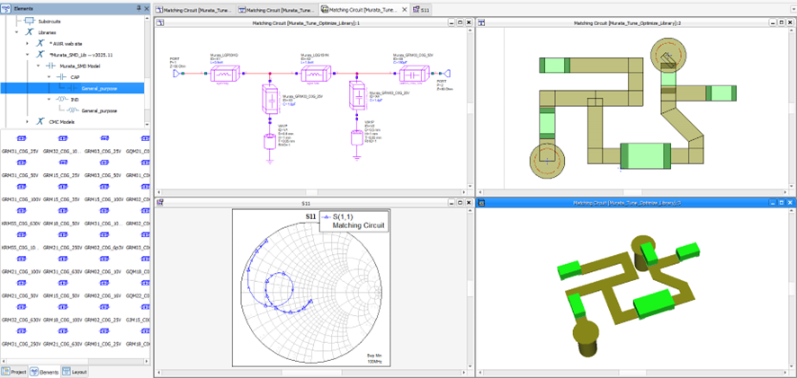
Figure 3. An RF filter in a tee configuration based on inductor and capacitor SMD components from Murata, wired together in a network simulated with Cadence Microwave Office.
The updated library can be downloaded from the Murata website. Please download the library and take advantage of the new tuning and optimization library.