

EVOLUTION OF SATELLITE COMMUNICATIONS
Satellite communication (satcom) systems are constantly moving toward higher frequency bands as there is an increasing need for wider bandwidth. Initial commercial satellite systems primarily operated in the C-Band (4 to 8 GHz) due to its favorable propagation characteristics, including low atmospheric attenuation and long-distance signal transmission. With the expansion of satcom during the 1980s and 1990s, higher frequency allocations such as Ku-Band (12 to 18 GHz) were introduced, enabling smaller user terminals and improved frequency reuse through narrower antenna beams. Later, the Ka-Band (26 to 40 GHz) became widely adopted for broadband satellite systems and high-throughput satellite (HTS) architectures, which employ multiple spot beams and more aggressive frequency reuse strategies to significantly increase system capacity.1-3
The continued growth of global broadband demand and the emergence of large satellite constellations have increasingly strained the available spectrum in traditional satcom bands. As a result, attention has shifted toward higher frequency bands, particularly the Q- and V-Bands (about 37 to 52 GHz). These bands offer substantially larger contiguous bandwidths than lower frequency allocations, making them attractive for satellite feeder links between gateway stations and satellites in next-generation HTS systems.4,5 By moving the high-capacity feeder links to Q/V-Band frequencies, satellite operators can preserve lower frequency bands such as Ka-Band for user terminals while significantly increasing overall network throughput.
Several experimental satellite missions and research programs have investigated the feasibility of Q/V-Band satcom. Demonstration programs such as the Alphasat Aldo Paraboni payload have been used to study propagation effects, channel behavior and adaptive communication techniques in Q/V-Band satellite links. These experiments have provided valuable insights into the performance of mmWave satellite channels and have helped validate the potential of Q/V-Band frequencies for future broadband satellite networks.6,7
The design of microwave hardware operating at mmWave frequencies presents additional engineering challenges, including higher component losses, increased sensitivity to manufacturing tolerances and the need for compact and highly integrated antenna feed networks. These considerations drive ongoing research into high performance microwave components such as orthomode transducers, polarizers and diplexers capable of supporting wideband dual polarized operation in Q/V-Band antenna systems.5,8,9
Q/V-BAND DUAL CIRCULAR POLARIZED FEED SYSTEM FOR SATCOM APPLICATIONS
Modern satcom systems increasingly rely on higher frequency bands to meet the growing demand for bandwidth and data throughput. In particular, Q/V-Band frequencies are becoming important for next-generation gateway and feeder link applications due to the large availability of spectrum.10-12 These systems often require wideband antenna architectures capable of supporting multiple frequency bands while maintaining high polarization purity and efficient signal separation between transmit and receive paths.
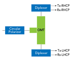
Figure 1 Block diagram of the feed system.
To meet these requirements, advanced microwave feed networks are required to manage polarization generation and frequency separation within compact antenna systems. Compared with conventional two-port architectures, Q/V-Band four-port microwave networks enable simultaneous transmit and receive operation, significantly improving communication efficiency and system capacity. The block diagram of the system is shown in Figure 1. Such networks are commonly implemented in dual-circular-polarization feed systems for high frequency satcom antennas.
A four-port circularly polarized microwave network designed for shared transmit and receive operation must perform three primary functions: polarization isolation, frequency duplexing (separation of transmitting and receiving frequency bands) and circular polarization synthesis. These functions ensure proper generation of circular polarization while effectively separating the uplink and downlink signals to minimize interference between the transmit and receive paths.
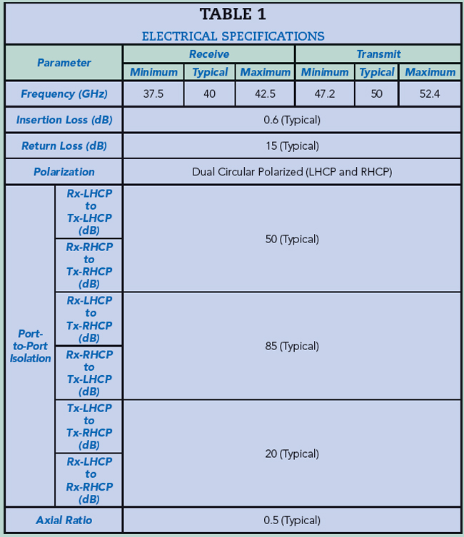
Eravant has developed a Q/V-Band feed system (model number SAU-403503854-22-DCP1) that integrates all of these functions as an assembly of a polarizer, OMT and two diplexers. The system is designed to operate within satcom frequency bands, supporting uplink operations at 47.2 GHz and 52.4 GHz and a downlink at 37.5 to 42.5 GHz. Based on the input port, the system can generate a left-hand or right-hand circularly polarized signal for the transmit or receive channels. The system provides a low insertion loss of about 0.6 dB and high port-to-port isolation of about 50 to 80 dB, depending on the channel configuration tested, and an axial ratio of 0.5 dB, ensuring high polarization purity. Additionally, the entire assembly is enclosed with weather-resistant housing, allowing the system to operate reliably in outdoor environments. The full electrical specifications of the feed system are listed in Table 1.
OMT ARCHITECTURE SELECTION
A key design objective for the feed system was to achieve high electrical performance across the entire bandwidth while maintaining a compact, weather-resistant mechanical structure. In typical reflector antenna systems, the feed network is located directly behind the feed horn and sub-reflector assembly, making physical size and weight important factors.
The initial design for the OMT used a symmetric Bøifot OMT, which is commonly used in high performance polarization duplexing applications due to its excellent isolation and broadband characteristics. However, the input port orientation was orthogonal to each other, making system integration difficult. Additionally, typical Bøifot OMTs have a square antenna port, necessitating waveguide transitions to connect the polarizer.
To meet the compact structure requirement and minimize the use of additional components, a turnstile orthomode transducer with a circular antenna port was used.13 The turnstile configuration uses a junction that naturally divides the electromagnetic fields into orthogonal polarization components. This rotational symmetry provides excellent amplitude and phase balance between polarization channels, enabling strong polarization over a wide frequency range. The symmetric structure also helps suppress unwanted mode conversion, which is particularly important for maintaining polarization purity at mmWave frequencies. This design ensures that the input ports are coplanar, allowing the two diplexers to remain in the same plane and facilitating system integration. Another advantage of the turnstile architecture is its compatibility with circular waveguide antenna interfaces. The circular antenna port allows the polarizer to be connected directly to the OMT, creating a compact and mechanically straightforward feed assembly. By maintaining a symmetric circular interface at the antenna side, the design preserves the natural field distribution (TE11) within the circular waveguide while minimizing structural complexity. This approach reduces the overall feed length and improves mechanical robustness, both of which are beneficial when integrating the feed system into reflector antenna assemblies. The measured performance versus simulated performance of the OMT is shown in Figure 2, and the photo of the developed OMT is shown in Figure 3.
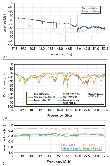
Figure 2 Simulated and measured performance of the OMT, isolation vs. frequency (a), return loss vs. frequency (b), insertion loss vs. frequency (c).
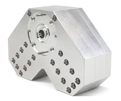
Figure 3 Photo of the developed OMT.
POLARIZER DESIGN
Another important design consideration for the feed system was the selection of the circular polarizer architecture. Several polarizer implementations were evaluated, including corrugated polarizers and dielectric (Duroid-based) polarizers, both of which are commonly used in wideband mmWave antenna systems. Corrugated polarizers can provide very broad bandwidth performance and are often used in applications where coverage of the entire waveguide band is required. However, maintaining very low axial ratio performance with corrugated structures can be challenging, particularly when compact geometries are required. The advantage of the corrugated design is its consistency, and it is preferred for a design for manufacturing process. Dielectric polarizers can also be used; however, the dielectric constant stability and loss issues of the dielectric slab can pose significant design challenges. In addition, the manufacturing process can be tedious, and the required skills can be a limiting factor in consistently achieving high performance.
To balance performance, manufacturability and design complexity, the final implementation employs a quad-ridge circular waveguide polarizer.12 These are well-suited for mmWave feed networks because they provide a good compromise between bandwidth, axial ratio performance, manufacturability and mechanical simplicity. By carefully optimizing the stepped waveguide structure for the operating Q/V-Band frequency ranges, the design achieves low axial ratio performance while maintaining a compact geometry compatible with the integrated feed assembly. The resulting polarizer provides stable circular polarization generation while supporting the overall objective of a compact and mechanically robust feed system. The measured performance versus simulated performance of the polarizer is shown in Figure 4, and the photo of the developed polarizer is shown in Figure 5.
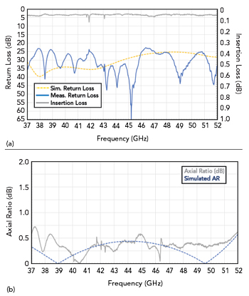
Figure 4 Simulated and measured performance of the polarizer, insertion loss and return loss vs. frequency (a), axial ratio vs. frequency (b).
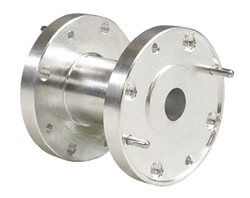
Figure 5 Photo of the developed polarizer.