

DIPLEXER DESIGN
Lastly, the feed network’s final component is the diplexer used to separate the transmission and receiving frequency bands. Traditional waveguide diplexers are typically implemented using two bandpass filters connected through a T-junction. While this configuration is relatively straightforward when the passbands are narrow, designing two wideband bandpass filters that operate efficiently in proximity becomes significantly more challenging when the required bandwidth increases.
To address this challenge, the diplexer used in this design employs sidewall coupling within the main waveguide structure. By carefully controlling the dimensions of the coupling waveguide, lower frequency signals produce a highpass response at the coupled port. This architecture simplifies the overall diplexer design by reducing the need for multiple independent bandpass filters while still achieving strong isolation between the transmit and receive channels. Additional matching steps are incorporated within the coupling section to improve high frequency matching, while the overall rejection characteristics can be adjusted by controlling the length of the coupling waveguide. The measured performance is compared with the simulated performance in Figure 6, and the photo of the developed diplexer is shown in Figure 7.
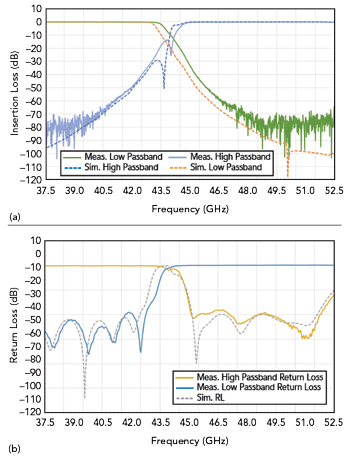
Figure 6 Simulated and measured performance of the diplexer, passband performance vs. frequency (a) and return loss vs. frequency (b).
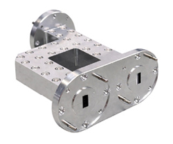
Figure 7 Photo of the developed diplexer.
MEASURED PERFORMANCE
To validate the performance of the feed system, the assembled unit was tested across the operating Q/V-Band frequency ranges. Measurements were performed to evaluate key parameters, including return loss, insertion loss, port isolation and axial ratio. The measured results demonstrate good agreement with the simulated performance and confirm that the feed network maintains strong polarization purity and isolation across the operating bandwidth.
The measured RF performance of the feed system is shown in Figures 8 and 9. The insertion loss across the passbands is about 0.6 dB typical, indicating efficient signal transmission through the feed network. The return loss is measured to be about 15 dB typical across the operating bandwidth, demonstrating good impedance matching at the ports. Polarization isolation between RX-R and RX-L, and between TX-R and TX-L, is measured at about 30 dB typical. Isolation between the transmit and receive channels for the same polarization (TX-L to RX-L and TX-R to RX-R) is measured to be about 50 dB typical. In addition, cross-channel isolation between the opposite polarization transmitting and receiving paths (TX-R to RX-L and TX-L to RX-R) typically exceeds 85 dB, confirming strong isolation between signal paths within the integrated feed system. The measured axial ratio is about 0.5 dB typical across the operating bandwidth, demonstrating high polarization purity of the circular polarization network.
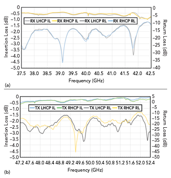
Figure 8 Measured return loss performance of the feed system; receive side insertion loss and return loss vs. frequency (a) and transmit side insertion loss and return loss vs. frequency (b).
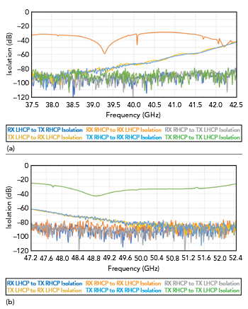
Figure 9 Measured isolation performance of the feed system: receive side isolation vs. frequency (a) and transmit side isolation vs. frequency (b).
SYSTEM INTEGRATION
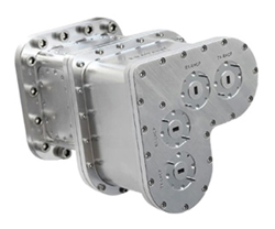
Figure 10 Photo of the developed Q/V-Band feed system.
The developed SAU-403503854-22-DCP1 feed system is shown in Figure 10. It is designed with a flexible architecture that allows straightforward integration into a wide range of antenna and ground station systems. The compact waveguide interface and modular feed network enable the unit to be readily incorporated into various reflector antenna configurations without significant modification to the existing RF front-end. In addition, the design can be adapted to meet specific customer requirements, including adjustments to frequency ranges, waveguide interfaces or mechanical configurations. This flexibility allows the feed system to be tailored for specialized satcom applications while maintaining the design’s core electromagnetic performance.
CONCLUSION
This article describes the design and implementation of a Q/V-Band dual circular polarized feed system for satcom applications. The integrated architecture combines a circular polarizer, turnstile orthomode transducer and diplexers into a compact feed network capable of supporting simultaneous transmit and receive operation across the Q/V-Band frequency ranges. Careful selection of the OMT, polarizer and diplexer architectures enabled the design to achieve low insertion loss, high port isolation and excellent polarization purity while maintaining a compact, weather-resistant structure suitable for reflector antenna integration and outdoor applications. Measured results validate the RF performance of the feed system and demonstrate its suitability for HTS communication systems operating at mmWave frequencies.
References:
- G. Maral and M. Bousquet, “Satellite Communications Systems: Systems,” Techniques and Technology, Fifth Ed., Wiley, 2009.
- T. Pratt, C. W. Bostian and J. Allnutt, Satellite Communications, Second Ed., Wiley, 2003.
- B. Evans, “The Role of Satellite Communications in Broadband Multimedia Networks,” International Journal of Satellite Communications and Networking, Vol. 22, 2004, pp. 247–268.
- R. De Gaudenzi, O. del Rio Herrero and A. Guillen i Fabregas, “Advances in Satellite Communications for Broadband Multimedia Services,” Proceedings of the IEEE, Vol. 99, No. 11, 2011, pp. 1853–1868.
- P. Angeletti et al., “Q/V-Band Satellite Communications: System Concepts and Technology Challenges,” International Journal of Satellite Communications and Networking, Vol. 30, No. 5, 2012, pp. 203–216.
- M. Luglio et al., “Exploitation of Q/V Band for Future Broadband Telecommunications Satellites,” International Journal of Satellite Communications and Networking, Vol. 27, No. 3–4, 2009, pp. 195–212.
- P. Angeletti et al., “The Alphasat Aldo Paraboni Q/V Band Communication Experiment,” International Journal of Satellite Communications and Networking, 2015.
- “ITU-R Recommendation P.618–13,” Propagation Data and Prediction Methods Required for the Design of Earth-Space Telecommunication Systems, ITU.
- “Aldo Paraboni Q/V Band Payload,” ESA, Jan. 21, 2014, Web: https://www.esa.int/Applications/Connectivity_and_Secure_Communications/Alphasat/Aldo_Paraboni_Q_V_Band_Payload.
- S. Jain, P. Srivastava, P. K. Srinivasan and R. R. Yagnik, “Q/V Band Earth Station Establishment- Testing and Challenges,” 2019 IEEE Indian Conference on Antennas and Propagation (InCAP), Ahmedabad, India, 2019, pp. 1–4, doi: 10.1109/InCAP47789.2019.9134630K.
- K. Yegin and P. Gouws, “Q/V-Band Frequency Converters for Next-Generation Stacom Systems,” Microwave Journal, Feb. 2026, Web: https://www.microwavejournal.com/articles/45338-q-v-band-frequency-converters-for-next-generation-satcom-systems.
- A. Tribak, A. Mediavilla, J. L. Cano, M. Boussouis and K. Cepero, “Ultra-broadband low axial ratio corrugated quad-ridge polarizer,” Proc. European Microwave Conference (EuMC), 2009, pp. 73–76.
- I. T. C. Yebes Observatory, “31.5–50 GHz Turnstile-Based WR22 Orthomode Transducer for the Nanocosmos Q-band Receiver,” Technical Report IT-CDT-2017-1, 2017.