
A novel circularly polarized antenna is based on a nonuniform metasurface (NMS). The baseline antenna is a uniform metasurface (UMS) layer with a slot antenna below. Asymmetric slotted patches in the center of the metasurface layer, defining the NMS, facilitate circular polarization (CP). To further enhance CP properties, an improved NMS (INMS) removes four patches at the corners of a 4 × 4 NMS array. Measurements demonstrate a -10 dB impedance bandwidth of 2.3 GHz (from 4.3 to 6.6 GHz) and two 3 dB axial ratio (AR) bandwidths of 400 MHz (from 5.1 to 5.5 GHz) and 300 MHz (from 6.2 to 6.5 GHz). Peak gain is 9.6 dBiC. Characteristic mode analysis (CMA) explores its modal behaviors. This configuration excites two orthogonal modes, producing CP radiation and the emergence of an additional AR minimum contributing to its broadband performance. Its performance makes it suitable for applications such as military and civilian communication, as well as point-to-point links.
CP has emerged as a crucial advancement in modern wireless communication infrastructure, particularly for establishing reliable point-to-point connections, owing to its inherent ability to suppress multipath interference and minimize polarization misalignment issues. The telecommunications industry’s escalating requirements for antenna systems that simultaneously deliver enhanced gain, expanded frequency coverage and broader 3 dB AR beamwidth have driven innovations in antenna design methodologies.
Among these innovations, metasurface-based solutions have demonstrated remarkable efficacy in both generating and optimizing CP radiation characteristics. This has spawned numerous successful metasurface-enhanced antenna designs exhibiting superior wideband CP performance characteristics.1-8 However, in conventional metasurface antenna designs, cell arrangements are usually uniformly configured. This limits radiation performance and presents significant difficulty in achieving dual-band CP radiation.9,10
To address these issues, an INMS architecture that enables precise electromagnetic field distribution control is proposed here. This approach improves radiation characteristics while simultaneously enhancing gain and increasing bandwidth. CMA provides insight into the antenna’s radiation mechanisms, yielding results that align closely with both simulated and measured performance.
INMS DESIGN
In the initial design phase, a UMS antenna is developed. The structure (see Figure 1) is a multilayer design comprising dual dielectric substrates, dual metallic layers and an integrated feed. The vertical stack, from top to bottom, includes the UMS layer, primary dielectric substrate, slotted ground plane, secondary dielectric substrate and feed network. Both dielectric substrates are 55 × 55 mm Duroid with εr = 2.2 and tanδ = 0.0009. Electromagnetic simulation of the UMS configuration using Ansys HFSS shows performance limitations in electromagnetic wavefront control, resulting in a discontinuous impedance bandwidth and poor AR performance (see Figure 2).
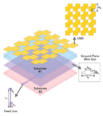
Figure 1 UMS antenna configuration.
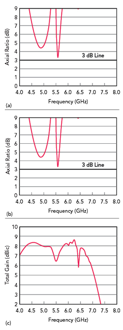
Figure 2 UMS antenna simulations: |S11| (a), AR (b) and total gain (c).
To enhance the antenna’s CP radiation characteristics, an NMS configuration (see Figure 3) incorporates rectangular slots angled at 45 degrees etched into the central 2 × 2 corner-cut square patches to improve linear-to-CP conversion efficiency. The positively sloped 45-degree orientation facilitates optimal CP radiation. Parametric analysis using Ansys HFSS simulations reveals that a slot length of 11 mm and a width of 1.5 mm result in improvements in both AR and impedance bandwidth (see Figure 4).
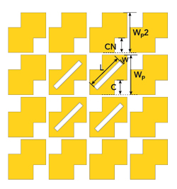
Figure 3 NMS configuration.
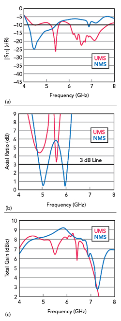
Figure 4 INMS configuration.
This design achieves a continuous impedance bandwidth of 1.26 GHz (from 4.19 to 5.45 GHz) and AR bandwidths of 0.34 GHz (from 4.89 to 5.23 GHz) and 0.21 GHz (from 5.85 to 6.06 GHz) with minimum AR values below 1 dB. These simulation results provide compelling evidence of the NMS structure’s capability to enhance antenna radiation characteristics. Comparative analysis with the UMS-based design reveals marked improvements in both radiation performance and CP properties.
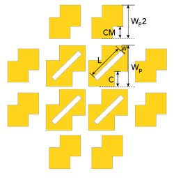
Figure 5 NMS antenna simulations: |S11| (a), AR (b) and total gain (c).
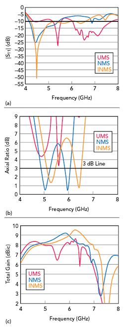
Figure 6 INMS antenna simulations: |S11| (a), AR (b) and total gain (c).
To further optimize performance, an INMS configuration removes four corner-positioned patches (see Figures 5 and 6). The modified design exhibits a wider impedance bandwidth of 1.73 GHz (from 4.24 to 5.97 GHz). The AR bandwidths are now 0.35 GHz (from 5.10 to 5.45 GHz) and 0.24 GHz (from 6.27 to 6.51 GHz). Final optimized antenna dimensions are listed in Table 1. Simulated far-field normalized radiation patterns at 5 GHz are symmetrical with minimal back lobe radiation (<-10 dB) and low cross-polarization levels (< -30 dB) in both xoz and yoz planes (see Figure 7).
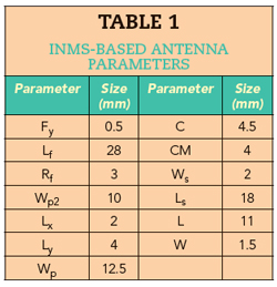
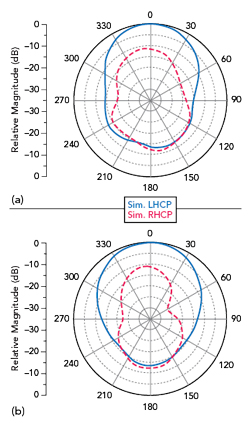
Figure 7 Simulated main lobe antenna patterns at 5 GHz in the xoz plane (a) and the yoz plane (b).