
INMS MODE BEHAVIOR ANALYSIS USING CMA
The establishment of CP requires simultaneous excitation of two orthogonal modes satisfying four fundamental criteria: 1) modal significance values exceeding 0.707 for both modes with comparable magnitudes, 2) characteristic angle (CA) phase differential approximating 90 degrees, 3) orthogonal surface current distributions and 4) coincident maximum radiation directions.
Detailed analysis and optimization of modal significance values (Figure 8a), CAs (Figure 8b), surface current distributions and radiation patterns are conducted using CST 2022’s multilayer computational solver. Simulation reveals five distinct modal behaviors with resonant frequencies at 5.21, 5.93, 5.92, 5.78 and 6.43 GHz, corresponding to unity modal significance values. Modes 1 and 2 emerge as primary operational modes. Surface current distribution analysis reveals diagonal current flow patterns. Both modes demonstrate consistent z-axis aligned radiation patterns, while the remaining modes exhibit anomalous current distributions. This conclusively identifies Modes 1 and 2 as an orthogonal mode pair capable of generating optimal CP.
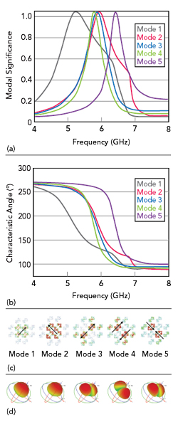
Figure 8 INMS modal behavior: modal significance values (a) CAs (b) surface currents (c) and radiation patterns at 5 GHz (d) of the first five modes.
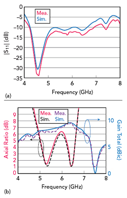
Figure 9 Antenna simulated and measured |S11| (a), AR and total gain (b).
SIMULATION AND MEASUREMENT
A prototype INMS antenna is characterized with near-field measurements using a vector network analyzer and far-field measurements in an anechoic chamber. Figure 9a shows a measured 2.3 GHz, -10 dB impedance bandwidth (from 4.3 to 6.6 GHz) with a resonance depth of -33.6 dB, slightly better than the simulation. The measured 3 dB AR bandwidth (see Figure 9b) covers two distinct frequency bands (from 5.1 to 5.5 GHz and 6.2 to 6.5 GHz), showing a slight improvement over simulated values while maintaining overall consistency. The gain curve shows a measured peak gain of 9.58 dB at 6.4 GHz, close to the simulated peak, occurring within the -10 dB impedance bandwidth.
Radiation patterns in the xoz and yoz planes at 5.3 GHz are shown in Figure 10. Both xoz- and yoz-plane cross-polarization levels are below -30 dB. Three dB beamwidths are 75 degrees (from -30 to 45 degrees) and 70 degrees (from -45 to 25 degrees) in the xoz and yoz planes, respectively.
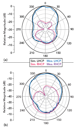
Figure 10 Simulated and measured radiation patterns at 5.3 GHz in the xoz plane (a) and the yoz plane (b).
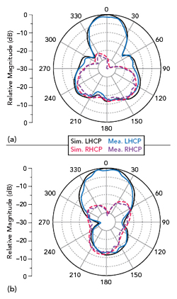
Figure 11 Simulated and measured radiation patterns at 6.35 GHz in the xoz plane (a) and the yoz plane (b).
Radiation patterns in the xoz and yoz planes at 6.35 GHz are shown in Figure 11. Both xoz- and yoz-plane cross-polarization levels are below -30 dB. Three dB beamwidths are 37.3 degrees (from -18.5 to 18.8 degrees) and 50 degrees (from -25 to 25 degrees) in the xoz and yoz planes, respectively. Close agreement between measured and simulated results is observed.
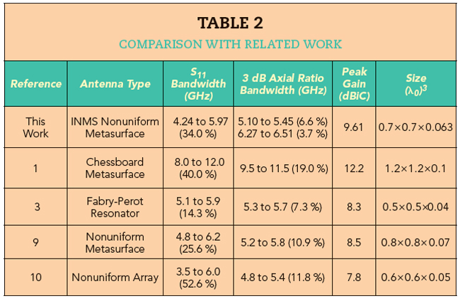
Table 2 compares the performance of this antenna with related studies.
CONCLUSION
A circularly polarized antenna design incorporates an NMS. CP radiation enhancement is achieved with an INMS configuration, consisting of a 2 × 2 array of central corner-cut slotted patches surrounded by peripheral corner-cut patches. Electromagnetic simulation validates the antenna’s radiation characteristics, while CMA provides a theoretical basis for the observed performance. CMA demonstrates that the INMS configuration achieves enhanced CP bandwidths compared to the conventional UMS design. This is attributed to its capacity to better satisfy modal significance and CA requirements. This antenna design is suitable for implementation in advanced communication systems and point-to-point link applications.
References
- K. Li, Y. Liu, Y. Jia and Y. J. Guo, “A Circularly Polarized High Gain Antenna with Low RCS Over a Wideband Using Chessboard Polarization Conversion Metasurfaces,” IEEE Transactions on Antennas and Propagation, Vol. 65, No. 8, August 2017, pp. 4288–4292.
- Y. Huang, L. Yang, J. Li, Y. Wang and G. Wen, “Polarization Conversion of Metasurface for the Application of Wideband Low-Profile Circular Polarization Slot Antenna,” Applied Physics Letters, Vol. 109, No. 5, August 2016.
- Z. -G. Liu, Z. -X. Cao and L. -N. Wu, “Compact Low-Profile Circularly Polarized Fabry-Perot Resonator Antenna Fed by Linearly Polarized Microstrip Patch,” IEEE Antennas and Wireless Propagation Letters, Vol.15, July 2015, pp. 524–527.
- Z. Wu, L. Li, Y. Li and X. Chen, “Metasurface Superstrate Antenna with Wideband Circular Polarization for Satellite Communication Application,” IEEE Antennas and Wireless Propagation Letters, Vol. 15, June 2015, pp. 374–377.
- H. L. Zhu, S. W. Cheung, K. L. Chung and T. I. Yuk, “Linear-to-Circular Polarization Conversion using Metasurface,” IEEE Transactions on Antennas and Propagation, Vol. 61, No. 9, September 2013, pp. 4615–4623.
- Q. Chen and H. Zhang, “Dual-Patch Polarization Conversion Metasurface-Based Wideband Circular Polarization Slot Antenna,” IEEE Access, Vol. 6, November 2018, pp. 74772–74777.
- P. Xie, G. Wang, H. Li and J. Liang, “A Dual-Polarized Two-Dimensional Beam-Steering Fabry-Perot Cavity Antenna with a Reconfigurable Partially Reflecting Surface,” IEEE Antennas and Wireless Propagation Letters, Vol. 16, June 2017, pp. 2370–2374.
- Q. Chen and H. Zhang, “High-Gain Circularly Polarized Fabry-Pérot Patch Array Antenna with Wideband Low-Radar-Cross-Section Property,” IEEE Access, Vol. 7, January 2019, pp. 8885–8889.
- X. Gao, S. Yin, G. Wang, C. Xue and X. Xie, “Broadband Low-RCS Circularly Polarized Antenna Realized by Nonuniform Metasurface,” IEEE Antennas and Wireless Propagation Letters, Vol. 21, No. 12, December 2022, pp. 2417–2421.
- J. Cui, X. Zhao and W. Sheng, “Low Profile and Broadband Circularly Polarized Metasurface Antenna Based on Nonuniform Array,” AEU-International Journal of Electronics and Communications., Vol. 156, November 2022.